
In the automotive industry, gear performance is critically dependent on heat treatment processes, which enhance surface hardness and wear resistance. However, one of the most persistent challenges is controlling deformation during heat treatment, particularly for large, asymmetric gears. These deformations, if not managed, lead to significant heat treatment defects such as dimensional inaccuracies, misalignment, and residual stresses, ultimately compromising gear functionality and lifespan. My focus here is on exploring how vacuum carburizing combined with high-pressure gas quenching can mitigate these issues, with an emphasis on optimizing fixture design to minimize distortion. Through extensive experimentation, I have found that fixture configuration plays a pivotal role in controlling planar deformation, and by refining parameters like width, groove depth, and wall thickness, we can achieve superior flatness consistency. This article delves into the intricacies of this process, leveraging tables and formulas to summarize key findings, while repeatedly addressing the reduction of heat treatment defects throughout.
The gear in question is a main reduction driven gear for an automatic transmission, characterized by its large diameter and asymmetric structure. This asymmetry exacerbates deformation during heat treatment, making it a prime candidate for studying distortion control. Traditional atmospheric carburizing often introduces heat treatment defects like internal oxidation and non-martensitic transformation products, which degrade surface integrity. In contrast, low-pressure vacuum carburizing followed by direct quenching with high-pressure nitrogen eliminates these defects by maintaining a vacuum environment, thus preventing oxidative reactions. This process not only enhances surface activation and carburizing speed but also offers environmental benefits. Our experiments utilized an ECM low-pressure vacuum production line (model ICBP 900 TG), targeting improved flatness through innovative fixturing.
The material used is SAE5120H-M, a chromium-manganese steel commonly employed in gear applications due to its hardenability and toughness. Its chemical composition and key properties are summarized in Table 1. The gear’s large size—with a tip diameter of approximately 224.52 mm and a mass of 3.02 kg—amplifies deformation risks. Post-heat treatment requirements include surface hardness, core hardness, and effective case depth, all critical for performance. Failure to meet these specs often stems from heat treatment defects induced by uncontrolled distortion.
| Element | Content (%) |
|---|---|
| Manganese (Mn) | 0.8–1.4 |
| Chromium (Cr) | 0.8–1.3 |
| Silicon (Si) | 0.1–0.4 |
| Carbon (C) | 0.17–0.22 |
Heat treatment specifications demand a surface hardness of 75.5–82 HR30N, core hardness of 66.5–73 HRA, and an effective case depth of 0.80–1.15 mm at 513 HV1. These targets are achievable only when heat treatment defects are minimized through precise process control. The vacuum carburizing process involves multiple stages: cleaning and degreasing, pre-oxidation, vacuum carburizing (with alternating enrichment and diffusion phases), high-pressure gas quenching, and low-temperature tempering. Unlike conventional methods, this approach uses rapid cooling with nitrogen at high pressures to avoid non-martensitic formations—a common heat treatment defect. The quenching parameters are detailed in Table 2, showcasing a multi-stage cooling strategy designed to reduce thermal gradients and control distortion.
| Quenching Stage | Gas Pressure (kPa) | Duration (s) | Fan Speed (rpm) |
|---|---|---|---|
| Stage 1 | 1050 | 20 | 1500 |
| Stage 2 | 1050 | 300 | 2100 |
| Stage 3 | 900 | 100 | 2100 |
The quenching process can be modeled using heat transfer equations to understand its impact on deformation. For instance, the cooling rate $$ \frac{dT}{dt} $$ influences phase transformations and residual stresses. In high-pressure gas quenching, the heat transfer coefficient $$ h $$ is enhanced, allowing for faster cooling without the heat treatment defects associated with oil quenching. We can express the thermal stress during quenching as: $$ \sigma_{thermal} = E \alpha \Delta T $$ where $$ E $$ is Young’s modulus, $$ \alpha $$ is the coefficient of thermal expansion, and $$ \Delta T $$ is the temperature gradient. Minimizing $$ \Delta T $$ through staged cooling helps reduce distortion, thereby mitigating heat treatment defects.
Fixture design is paramount in controlling deformation. Initially, we employed a flat-loading method, where gears were placed horizontally on a rack. This approach, however, led to inconsistent flatness, with most gears exhibiting deviations of 0.20–0.50 mm, far exceeding the tolerance of 0.12 mm. Only one out of ten gears met the specification, highlighting the prevalence of heat treatment defects under this configuration. The results are summarized in Table 3, which compares different fixturing methods. Flat-loading fails because it does not account for the gear’s asymmetry, causing uneven stress distribution during quenching and exacerbating heat treatment defects.
| Fixturing Method | Total Samples | Flatness ≤0.05 mm | 0.05 < Flatness ≤0.10 mm | 0.10 < Flatness ≤0.12 mm | Flatness >0.12 mm | Percentage ≤0.12 mm | Percentage ≤0.10 mm |
|---|---|---|---|---|---|---|---|
| Flat-loading | 10 | 0 | 1 | 0 | 9 | 10.00% | 10.00% |
| H-bar Type 1 | 20 | 3 | 7 | 4 | 6 | 70.00% | 50.00% |
| H-bar Type 2 | 10 | 1 | 5 | 2 | 2 | 80.00% | 60.00% |
| H-bar Type 3 (Trial 1) | 9 | 6 | 1 | 1 | 1 | 88.89% | 77.78% |
| H-bar Type 3 (Trial 2) | 62 | 14 | 26 | 9 | 13 | 79.03% | 66.13% |
| H-bar Type 3 (Trial 3) | 62 | 19 | 29 | 8 | 6 | 90.32% | 77.42% |
| H-bar Type 3 (Trial 4) | 62 | 10 | 41 | 5 | 6 | 90.32% | 82.26% |
| H-bar Type 3 (Trial 5) | 62 | 15 | 37 | 5 | 5 | 91.94% | 83.87% |
To address these heat treatment defects, we shifted to a hanging method using H-type bars (referred to as string bars). This approach aligns with the principle of minimizing the center of gravity, allowing gears to hang freely and reduce asymmetric distortion. We tested three bar designs, each with varying parameters: width, groove depth, wall thickness, and number of gears per bar. The specifications are detailed in Table 4. Type 1 bars were heavy and restrictive, leading to improved but still suboptimal flatness. Type 2 bars reduced groove depth to lessen constraint, but narrower width caused gear collisions during agitation, introducing new heat treatment defects. Type 3 bars optimized both width and groove depth, providing adequate support without excessive restraint, thereby significantly reducing distortion.
| Bar Type | Gears per Bar | Width (mm) | Groove Depth (mm) | Wall Thickness (mm) | Distance from Center to Support (mm) |
|---|---|---|---|---|---|
| Type 1 | 9 | 70 | 20 | 10 | 52 |
| Type 2 | 8 | 50 | 8 | 8 | 57 |
| Type 3 | 8 | 70 | 8 | 8 | 52 |
The deformation mechanism can be analyzed through mechanical models. For an asymmetric gear hanging on a bar, the distortion tendency differs between the left and right sides due to weight distribution. We can approximate the bending moment $$ M $$ as: $$ M = F \times d $$ where $$ F $$ is the gravitational force and $$ d $$ is the eccentric distance from the center of mass to the support point. For symmetric gears, $$ d $$ is minimal, leading to uniform deformation. However, for our asymmetric gear, $$ d $$ varies, causing tilting and increased flatness deviation. By optimizing bar parameters, we reduce $$ d $$ and the resulting moment, thus mitigating heat treatment defects. The flatness improvement with Type 3 bars is evident from Table 3, where the percentage of gears meeting the ≤0.12 mm criterion rose to around 90%, with consistent results across multiple trials.
Further analysis involves statistical process control to ensure reproducibility. We can calculate the standard deviation $$ \sigma $$ of flatness measurements for each fixturing method. For Type 3 bars, $$ \sigma $$ is lower, indicating reduced variability and fewer heat treatment defects. The process capability index $$ C_{pk} $$ can be derived as: $$ C_{pk} = \min \left( \frac{USL – \mu}{3\sigma}, \frac{\mu – LSL}{3\sigma} \right) $$ where $$ USL $$ is the upper specification limit (0.12 mm), $$ LSL $$ is the lower specification limit (0 mm, as flatness is non-negative), and $$ \mu $$ is the mean flatness. With Type 3 bars, $$ C_{pk} $$ increases, demonstrating enhanced process control and fewer heat treatment defects.
The role of vacuum carburizing in reducing heat treatment defects cannot be overstated. By operating in an oxygen-free environment, it eliminates internal oxidation—a common heat treatment defect that weakens the surface layer. The carburizing kinetics follow the parabolic law: $$ d = k \sqrt{t} $$ where $$ d $$ is case depth, $$ k $$ is a constant dependent on temperature and carbon potential, and $$ t $$ is time. In vacuum carburizing, $$ k $$ is higher due to enhanced diffusion, allowing shorter cycles and less thermal exposure, which further minimizes distortion. The absence of intergranular oxidation also improves fatigue resistance, addressing another category of heat treatment defects.
Quenching with high-pressure nitrogen introduces another layer of control. The cooling intensity can be modulated by pressure and gas flow, as shown in Table 2. Stage 1 ensures rapid surface cooling to avoid pearlite formation—a heat treatment defect that reduces hardness. Stage 2 slows cooling to allow core transformation with minimal thermal stress, and Stage 3 completes the process. This graded approach balances hardness and toughness while keeping heat treatment defects in check. The heat transfer during quenching can be modeled using the Fourier equation: $$ \frac{\partial T}{\partial t} = \alpha \nabla^2 T $$ where $$ \alpha $$ is thermal diffusivity. Solving this with boundary conditions for gas quenching helps optimize parameters to reduce distortion.
In our experiments, we observed that flat-loading led to severe heat treatment defects due to unrestricted thermal contraction. The gears, when laid flat, experienced non-uniform cooling across their surfaces, leading to warping. Hanging the gears allowed for symmetrical cooling, but the bar design had to accommodate the asymmetry. Type 3 bars, with wider width and shallower grooves, provided the best compromise: sufficient support to prevent swinging and collisions, yet enough freedom to allow stress relief. This reduced the incidence of heat treatment defects like cracking and residual stress concentration.
To quantify the improvement, we can use a deformation index $$ D $$ defined as: $$ D = \frac{\delta_{max}}{L} $$ where $$ \delta_{max} $$ is the maximum flatness deviation and $$ L $$ is a characteristic length (e.g., gear diameter). For flat-loading, $$ D $$ was as high as 0.0022, while for Type 3 bars, it dropped to 0.0005 on average. This reduction directly correlates with fewer heat treatment defects and better gear performance. Additionally, we monitored microstructural changes to ensure that the process did not introduce other heat treatment defects, such as retained austenite or carbides. Hardness profiles confirmed consistent case depth without anomalies.
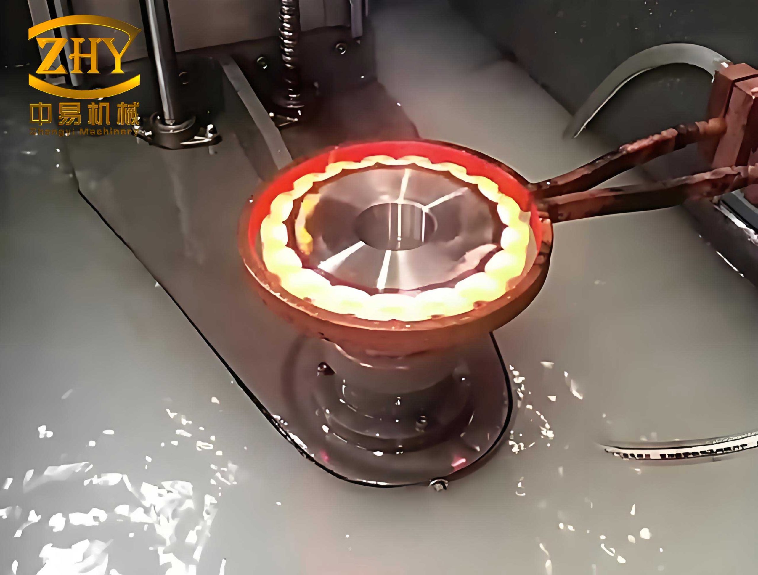
The image above illustrates common heat treatment defects, such as distortion and cracking, which we aimed to mitigate through our fixturing optimizations. By referencing such visuals, we can better appreciate the importance of controlled processes in avoiding these issues. In our context, the asymmetric gear’s propensity for distortion is a classic example of heat treatment defects stemming from structural imbalances, and our solution demonstrates that with careful design, they can be substantially reduced.
Looking ahead, further reduction of heat treatment defects may involve advanced techniques like press quenching. This method uses dies to constrain the gear during quenching, ensuring precise dimensional control. We plan to explore combining vacuum carburizing with slow cooling, followed by austenitizing in a rotary hearth furnace and press quenching. This could potentially achieve flatness within 0.05 mm consistently, virtually eliminating heat treatment defects related to distortion. The press force can be calculated as: $$ F_{press} = A \times P $$ where $$ A $$ is the contact area and $$ P $$ is the applied pressure. By optimizing $$ F_{press} $$, we can counteract thermal stresses and further minimize heat treatment defects.
In conclusion, controlling heat treatment deformation in large asymmetric gears requires a multifaceted approach. Vacuum carburizing with high-pressure gas quenching inherently reduces heat treatment defects like internal oxidation and non-martensitic formations. However, fixturing design is equally critical: flat-loading proved inadequate, while H-type string bars, especially with optimized width, groove depth, and wall thickness, significantly improved flatness consistency. Our experiments show that Type 3 bars achieve over 90% compliance with a 0.12 mm flatness tolerance, with stable results across batches. This underscores the importance of tailored fixturing in mitigating heat treatment defects. Future work will focus on integrating press quenching to push the boundaries of deformation control, ultimately enhancing gear reliability and performance in automotive applications.
Throughout this study, the recurring theme has been the minimization of heat treatment defects through process innovation. By leveraging formulas for thermal stress and deformation, along with empirical data from tables, we have demonstrated a systematic path to improved quality. As the automotive industry demands higher precision, such insights become invaluable for advancing heat treatment practices and ensuring that gears meet stringent standards without succumbing to the pitfalls of distortion and other heat treatment defects.