
I work on the forming of automobile rear axle pinion gears, and I am interested in replacing the conventional hammer drawing and die forging route with a cross wedge rolling plus die forging route. The pinion gears used in automobile rear axles are key parts in the power transmission system. They carry torque, transmit motion to the differential, and operate under repeated bending, torsion, and contact loading. Because the demand for such pinion gears is large, even a small improvement in billet manufacture can produce a large reduction in cost, energy consumption, and scrap. In my study, I focus on the billet-making stage of pinion gears, especially on how to produce a reliable rolled billet with cross wedge rolling and how to make the tooling more universal for different pinion gears.
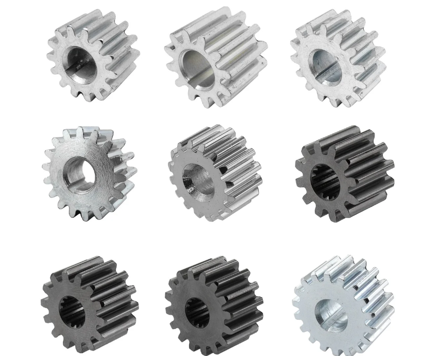
The traditional process that I want to improve is commonly described as hammer drawing followed by die forging. It requires heavy equipment, many blows, low production efficiency, poor dimensional accuracy, and low material utilization. For pinion gears, the conventional route often begins with bar stock that is drawn out on a hammer, then formed in a die forging press, and finally machined. This route is flexible, but it is not efficient for large-volume production of pinion gears. The repeated heating and handling also increase energy consumption and reduce consistency. Therefore, I propose a process in which cross wedge rolling provides a preform close to the required axisymmetric or conical shape of the pinion gears, and die forging then finishes the geometry. This combined route reduces the load on the die forging press, shortens the process chain, and improves material utilization.
Cross wedge rolling is an advanced forming technology for axisymmetric parts. It uses wedge-shaped tools that progressively penetrate and widen a cylindrical billet while the billet rotates between the tools. The process is well suited to shafts, axles, and preforms for pinion gears because it can distribute material along the axis, produce a favorable grain flow, and reduce flash. In my approach, I not only select cross wedge rolling for pinion gears but also optimize the part structure so that one set of cross wedge rolling dies can produce billets for several families of pinion gears. The main obstacle that I encounter is the rotation condition: if the friction torque is insufficient, the billet does not rotate, and it is simply flattened between the tools. I solve this problem by adding grooves on the side wedge surfaces of the cross wedge rolling dies. I compare semicircular and triangular groove sections, and I find that triangular grooves are more effective. I also study how process parameters influence the center damage value, because center damage is a major quality concern in cross wedge rolling of pinion gears.
The following table summarizes the difference between the conventional route and the route I propose for pinion gears. The comparison is written from the perspective of billet manufacture, because the finishing steps for pinion gears remain necessary after forming.
| Item | Conventional hammer drawing and die forging | Cross wedge rolling and die forging |
|---|---|---|
| Main billet operation | Hammer drawing, repeated blows, manual handling | Cross wedge rolling to a shaped preform |
| Equipment load | High tonnage and high impact | Lower die forging load because the preform is closer to the final shape |
| Production efficiency | Low, many operations per part | Higher, continuous rolling action |
| Material utilization | Low due to flash, scale, and machining allowance | Higher because the rolled billet is closer to the required pinion gear shape |
| Dimensional consistency | Limited by manual hammer control | Better because the rolling dies define the axial distribution |
| Tooling cost for pinion gears | High when many variants are forged separately | Can be reduced by structure optimization and universal rolling dies |
| Main technical risk | Low, but inefficient | Rotation stability and center damage must be controlled |
The geometry of the pinion gears is important because the shaft portion often contains steps. If every pinion gear variant has a different step position and step diameter, then every variant would require a different cross wedge rolling die. Die manufacturing is expensive, and for trial production or small batch production, this expense can remove the benefit of cross wedge rolling. Therefore, I optimize the part structure by removing the shaft steps and replacing them with a tapered shaft. The taper is chosen so that the subsequent die forging and machining can still produce the final pinion gears with sufficient machining allowance. I examine several types of pinion gears and find that the shaft inclination angle lies roughly between one and three degrees. To cover as many pinion gear variants as possible while keeping the rolling die simple, I select a rolled billet with a shaft inclination angle of about two degrees.
I define the taper of the rolled billet for pinion gears by a radius function. If the axial coordinate is \(z\), the initial radius is \(r_0\), and the inclination angle is \(\theta\), then the radius and diameter can be written as
$$ r(z)=r_0-z\tan\theta,\qquad D(z)=D_0-2z\tan\theta $$
where \(D_0\) is the initial diameter. The volume of the tapered billet must match the volume of the initial cylindrical billet if I neglect scale loss and flash. This gives the following volume balance for the pinion gears preform:
$$ V_0=\frac{\pi}{4}D_0^2L_0=\frac{\pi}{4}\int_0^L \left(D_0-2z\tan\theta\right)^2dz $$
For the cross wedge rolling stage, I also need a clear measure of deformation. The cross-sectional reduction ratio is one of the most useful quantities for pinion gears because it controls the amount of radial compression and axial material flow. I define it as
$$ Z=\frac{A_0-A_1}{A_0}\times 100\%=\left(1-\frac{D_1^2}{D_0^2}\right)\times 100\% $$
where \(A_0\) is the initial cross-sectional area and \(A_1\) is the reduced cross-sectional area. In my simulation and experiments, the reduction ratio is about \(64.4\%\). For a nominal initial diameter of \(50\,\text{mm}\), this reduction ratio corresponds to a reduced diameter of approximately \(29.8\,\text{mm}\). This level of reduction is large enough to create significant axial flow, but it also makes rotation stability and center damage important for pinion gears.
| Parameter | Symbol | Value or range | Role for pinion gears |
|---|---|---|---|
| Initial billet diameter | \(D_0\) | 50 mm | Defines the starting stock for cross wedge rolling |
| Reduction ratio | \(Z\) | 64.4% | Controls radial compression and axial flow |
| Shaft inclination angle | \(\theta\) | about 2° | Allows one rolling die family to cover several pinion gears |
| Forming angle | \(\alpha\) | 15° to 25° in trials | Controls wedge penetration and axial flow resistance |
| Widening angle | \(\beta\) | 7.5° to 8.5° in trials | Controls axial spreading rate and rolling time |
| Billet temperature | \(T_0\) | 1150 °C | Reduces flow stress for pinion gears |
| Roll angular velocity | \(\omega_r\) | 0.8 rad/s | Sets the peripheral speed and rolling time |
The cross wedge rolling tool geometry can be described by the forming angle and the widening angle. If the axial coordinate is \(z\), the wedge width caused by widening can be approximated by
$$ w(z)=z\tan\beta $$
and the wedge height caused by the forming angle can be approximated by
$$ h(x)=x\tan\alpha $$
where \(x\) is the coordinate along the wedge. These two angles determine the contact area, the rolling force, the axial velocity of the deforming material, and the tendency for center damage in pinion gears. A larger forming angle makes the wedge steeper, so the material resistance to axial flow increases. A larger widening angle makes the wedge wider per unit length, so the axial spreading rate increases. Both angles must be balanced against the rotation condition.
For stable cross wedge rolling of pinion gears, the billet must rotate continuously. The roll surface speed is
$$ v_r=\omega_r R_r $$
and the ideal workpiece rotational speed, if there is no slip, is
$$ \omega_w=\frac{2v_r}{D_w}=\frac{2\omega_r R_r}{D_w} $$
where \(R_r\) is the roll radius and \(D_w\) is the current workpiece diameter. In reality, slip occurs, and the rotation is controlled by the balance between the friction torque and the resisting torque. I write the rotation condition as
$$ \frac{M_f}{M_n}=\frac{\left(\mu+\Delta\mu_s\right)F_n R_w}{F_n a_n}=\frac{\left(\mu+\Delta\mu_s\right)R_w}{a_n}\ge 1 $$
where \(M_f\) is the driving friction torque, \(M_n\) is the resisting torque from the normal pressure, \(\mu\) is the base friction coefficient, \(\Delta\mu_s\) is the additional effective friction caused by the grooves, \(F_n\) is the normal force, \(R_w\) is the workpiece radius, and \(a_n\) is the moment arm of the normal force. This inequality can be rearranged as
$$ \mu+\Delta\mu_s\ge \frac{a_n}{R_w} $$
The term \(\Delta\mu_s\) is the reason I introduce grooves on the side wedge surfaces. The grooves increase the resistance to relative sliding and create mechanical interlocking. For pinion gears, the rotation condition is especially important at the beginning of rolling, when the billet is still nearly cylindrical and the contact area is small.
I build a finite element model of the cross wedge rolling process for pinion gears. The tools are treated as rigid bodies because their elastic deformation is small compared with the deformation of the billet. The billet is treated as a plastic body. The material is a carburizing steel suitable for pinion gears, and I use a temperature-dependent flow stress model. The mesh consists of about fifty thousand tetrahedral elements. The heat transfer coefficient between the workpiece and the tools is set to \(5\,\text{N}\cdot(\text{s}\cdot\text{mm}\cdot\text{°C})^{-1}\). The friction boundary condition is a constant shear factor model, which is often more suitable than Coulomb friction for hot metal forming. The initial simulation parameters are listed in the following table.
| Simulation parameter | Value | Remark for pinion gears |
|---|---|---|
| Initial billet temperature | 1150 °C | Hot forming regime |
| Roll angular velocity | 0.8 rad/s | Moderate rolling speed |
| Initial billet diameter | 50 mm | Matches the selected stock |
| Reduction ratio | 64.4% | Produces significant axial flow |
| Forming angle, initial trial | 25° | Steep wedge, high resistance |
| Widening angle, initial trial | 7.5° | Moderate spreading rate |
| Friction factor | 0.7 | Shear friction condition |
| Heat transfer coefficient | 5 N/(s·mm·°C) | Tool-workpiece interface |
| Mesh type | Tetrahedral | Good for complex contact |
| Number of elements | 50000 | Balance between accuracy and cost |
The thermal and mechanical fields are coupled. The heat conduction equation in the workpiece is
$$ \rho c_p \frac{\partial T}{\partial t}=k\nabla^2T+\dot{q}_{def} $$
where \(\rho\) is density, \(c_p\) is specific heat, \(k\) is thermal conductivity, and \(\dot{q}_{def}\) is the heat generated by plastic deformation. I approximate the deformation heating as
$$ \dot{q}_{def}=\eta_p \bar{\sigma}\dot{\bar{\varepsilon}}^p $$
where \(\eta_p\) is the fraction of plastic work converted into heat, \(\bar{\sigma}\) is the effective stress, and \(\dot{\bar{\varepsilon}}^p\) is the effective plastic strain rate. The shear friction stress at the interface is written as
$$ \tau_f=m k_s $$
where \(m\) is the friction factor and \(k_s\) is the shear yield stress of the material. For pinion gears, the friction condition is not only a matter of surface quality; it directly determines whether the billet rotates or flattens.
To evaluate internal quality, I use a damage indicator. The normalized damage value at the center of the pinion gears billet is calculated by integrating the tensile stress history over the effective plastic strain:
$$ D=\int_0^{\bar{\varepsilon}_f}\frac{\sigma^*}{\bar{\sigma}}d\bar{\varepsilon} $$
where \(\sigma^*\) is the maximum principal tensile stress, \(\bar{\sigma}\) is the effective stress, and \(\bar{\varepsilon}\) is the effective plastic strain. A larger \(D\) means a greater risk of internal void formation or central cracking. I track the center point because center damage is a common failure mode in cross wedge rolling of pinion gears. I also define a maximum center damage index as
$$ D_c=\max_t D(\mathbf{x}_c,t) $$
where \(\mathbf{x}_c\) is the location of the center point. This index allows me to compare different process parameters for pinion gears without relying only on visual inspection.
In the initial simulation, I observe a serious problem. After rolling begins, the first stage is the wedge penetration stage. The tools penetrate the billet and form a V-shaped groove. If rotation is stable, the billet should continue to rotate and the groove should widen gradually along the axis. However, in the initial trial, the billet soon stops rotating and is simply flattened between the upper and lower tools. The flattening is visible at the early, middle, and late times of the simulation. The main cause is that the friction torque is too small to satisfy the rotation condition. The forming angle is \(25^\circ\), and the side wedge surface area is limited, so the additional friction that could drive rotation is insufficient. The normal pressure is large, and the resisting torque dominates. Therefore, the billet is compressed radially instead of being rolled. This failure mode is unacceptable for pinion gears because it destroys the axisymmetric shape and produces severe internal damage.
| Rolling time | Observed behavior | Reason | Consequence for pinion gears |
|---|---|---|---|
| 1 s | Wedge penetration begins, V-shaped groove forms | Contact area still small | Rotation is not yet fully established |
| 6 s | Billet begins to flatten instead of rotating | Friction torque is less than resisting torque | Shape becomes non-axisymmetric |
| 12 s | Severe flattening between tools | Rotation condition is not satisfied | Pinion gear preform is unusable |
To increase the friction torque, I modify the side wedge surfaces of the dies. I add grooves so that the material must flow over and around the groove edges. This increases the resistance to sliding and raises the effective friction coefficient. I investigate two groove sections: a semicircular section and a triangular section. For the semicircular section, the area is
$$ A_s=\frac{1}{2}\pi r_s^2 $$
and the perimeter is
$$ P_s=\pi r_s $$
where \(r_s\) is the semicircle radius. For the triangular section, the area is
$$ A_t=\frac{1}{2}b h_t $$
and the perimeter is
$$ P_t=b+2\sqrt{\left(\frac{b}{2}\right)^2+h_t^2} $$
where \(b\) is the base width and \(h_t\) is the triangle height. The triangular groove has sharper edges and a larger perimeter-to-area ratio for a given depth. This sharper geometry produces more mechanical interlocking and a larger effective friction increment. I also reduce the forming angle from \(25^\circ\) to \(15^\circ\) in the grooved-die trials so that the side wedge surface area is larger and the grooves can be distributed over a wider region. The comparison of the two groove shapes is given in the next table.
| Feature | Semicircular groove | Triangular groove |
|---|---|---|
| Section area | \(A_s=\frac{1}{2}\pi r_s^2\) | \(A_t=\frac{1}{2}b h_t\) |
| Section perimeter | \(P_s=\pi r_s\) | \(P_t=b+2\sqrt{(b/2)^2+h_t^2}\) |
| Edge sharpness | Smooth, lower stress concentration | Sharp, higher interlocking effect |
| Effective friction increment | Moderate | Higher |
| Metal flow resistance | Lower | Higher |
| Rotation stability for pinion gears | Insufficient in the trial | Sufficient in the trial |
| Die wear risk | Lower | Higher, but manageable with proper material selection |
The simulation results show a clear difference between the two groove shapes. For the semicircular groove, the tracked points on the axial section initially accelerate to about \(200\,\text{mm/s}\), but then the velocity decreases as the wedge penetrates deeper. At about five seconds, the velocity approaches zero. This means that the friction increment from the semicircular groove is not enough to maintain rotation. The normal pressure continues to increase, and the resisting torque becomes dominant. For the triangular groove, the tracked points also accelerate to about \(200\,\text{mm/s}\), but then they settle to about \(100\,\text{mm/s}\) and remain positive until the later stage of rolling. The velocity decreases to zero only after the dies separate from the workpiece. This behavior shows that the triangular groove provides a stable rotation condition for pinion gears.
| Groove type | Initial velocity | Velocity during widening | Rotation stability | Final shape |
|---|---|---|---|---|
| Semicircular | about 200 mm/s | Decreases to zero near 5 s | Unstable | Flattening tendency |
| Triangular | about 200 mm/s | Stabilizes near 100 mm/s | Stable until die separation | Axisymmetric preform |
After selecting the triangular groove, I analyze the influence of the process parameters on center damage for pinion gears. The forming angle is the first parameter. When the forming angle increases, the wedge becomes steeper. The axial flow of metal becomes more difficult, so more material is displaced in the radial and tangential directions. This changes the stress state in the center of the billet. In my simulations, the damage curves for different forming angles follow similar paths. The slope is largest in the widening stage, then decreases in the later widening and sizing stages. At the end of rolling, the center damage value decreases slightly as the forming angle increases. This means that a larger forming angle can reduce the final center damage under the conditions I tested, although the effect is moderate. The reason is that a steeper wedge changes the contact geometry and the distribution of normal pressure, which can reduce the tensile stress component at the center for a given reduction ratio.
| Forming angle \(\alpha\) | Final center damage \(D_c\) | Trend | Comment for pinion gears |
|---|---|---|---|
| 15° | 0.92 | Higher | Softer wedge, more axial flow |
| 18° | 0.88 | Moderate | Balanced flow |
| 21° | 0.84 | Lower | Higher radial compression |
| 25° | 0.81 | Lowest in the set | Steep wedge, but rotation must be checked |
The widening angle is the second important parameter. In the widening stage, an increase in the widening angle makes the wedge wider per unit axial length. The axial velocity of the deforming metal increases, and the amount of deformation accumulated in the center increases. As a result, the center damage value during the widening stage becomes larger when the widening angle increases. However, the final damage values for different widening angles are not as different as the intermediate values. A larger widening angle also reduces the total rolling time, so the number of revolutions and the duration of the kneading action decrease. This can partially offset the damage increase. Therefore, I do not treat the widening angle as a simple parameter to maximize. Instead, I look for a window in which the pinion gears preform is produced in a short time without excessive center damage.
| Widening angle \(\beta\) | Damage in widening stage | Final damage \(D_c\) | Rolling time | Comment for pinion gears |
|---|---|---|---|---|
| 6.5° | Low | 0.86 | Longer | More revolutions, more kneading |
| 7.5° | Moderate | 0.84 | Moderate | Balanced condition |
| 8.5° | Higher | 0.83 | Shorter | Good productivity, but monitor center damage |
| 9.5° | High | 0.85 | Shortest | Risk of internal defects |
The interaction between forming angle and widening angle is also important for pinion gears. A large forming angle can reduce the final center damage, but it also increases the normal force and may make rotation more difficult. A large widening angle can shorten the process, but it raises the damage in the widening stage. Therefore, I use the triangular groove to improve rotation, and I select a moderate forming angle and a moderate widening angle. In the production validation, I use a forming angle of \(16.5^\circ\) and a widening angle of \(8.5^\circ\) with triangular grooves on the side wedge surfaces. This combination provides stable rotation and acceptable center damage for the pinion gears preform.
| Parameter combination | Rotation | Center damage | Shape quality | Production time |
|---|---|---|---|---|
| Small \(\alpha\), small \(\beta\) | Good | Moderate | Good | Long |
| Small \(\alpha\), large \(\beta\) | Good | Higher during widening | Acceptable | Short |
| Large \(\alpha\), small \(\beta\) | Risk of slip | Lower final damage | Good if rotation is stable | Moderate |
| Large \(\alpha\), large \(\beta\) | High slip risk | Mixed | Poor if slip occurs | Short but risky |
| Selected: \(\alpha=16.5^\circ\), \(\beta=8.5^\circ\), triangular groove | Stable | Acceptable | Clear contour | Efficient |
I validate the model by rolling pinion gears billets on a cross wedge rolling machine. The dies are manufactured with triangular grooves on the side wedge surfaces. The forming angle is \(16.5^\circ\), and the widening angle is \(8.5^\circ\). The billet is heated to \(1150^\circ\text{C}\), and the roll angular velocity is \(0.8\,\text{rad/s}\). The rolled workpiece has a clear contour, a well-formed shaft taper, and no visible flattening. The simulation and experimental results agree well. This validation confirms that the rotation condition can be satisfied by triangular grooves and that the selected process window is practical for pinion gears.
| Validation item | Simulation | Experiment | Agreement |
|---|---|---|---|
| Rotation stability | Stable | Stable | Good |
| Final shape | Axisymmetric with taper | Axisymmetric with taper | Good |
| Surface contour | Clear | Clear | Good |
| Flattening | None | None | Good |
| Center damage risk | Acceptable | No visible internal defect | Acceptable |
| Forming angle | 16.5° | 16.5° | Same |
| Widening angle | 8.5° | 8.5° | Same |
The industrial importance of this work for pinion gears is significant. By optimizing the part structure and removing the shaft steps, I can roll a tapered billet with a shaft inclination angle of about two degrees. This allows one cross wedge rolling die family to produce billets for several pinion gears variants. The die cost is therefore spread over more products. The rolling step reduces the amount of material that must be removed by machining, and it reduces the load on the die forging press. The triangular groove solves the rotation problem without requiring a complex auxiliary drive. The process window gives a practical route to stable rolling and acceptable center damage. For pinion gears production, these improvements can increase efficiency, reduce material waste, and improve consistency.
| Benefit | Mechanism | Effect on pinion gears production |
|---|---|---|
| Universal rolling dies | Remove shaft steps and use a two-degree taper | One die set covers multiple pinion gears variants |
| Higher material utilization | Cross wedge rolling produces a near-net preform | Less machining allowance and less flash |
| Lower die forging load | Preform is closer to the final pinion gears shape | Longer die life and lower press tonnage |
| Stable rotation | Triangular grooves on side wedge surfaces | Prevents flattening and ensures axisymmetric pinion gears billets |
| Controlled center damage | Selected forming and widening angles | Reduces internal defect risk in pinion gears |
| Shorter process chain | Replace hammer drawing with cross wedge rolling | Higher productivity and lower energy consumption |
I also consider the limitations of my approach. The triangular grooves increase the local contact pressure and may cause die wear. The groove geometry must be maintained during production, and the die material and heat treatment must be selected accordingly. The two-degree taper is a compromise; if a pinion gear family has a very different shaft angle, a different rolling die may still be required. The center damage model is based on a continuum damage indicator, so it is useful for comparing parameters but cannot replace destructive testing for safety-critical pinion gears. In future work, I would combine the cross wedge rolling model with a die forging model to evaluate the full process chain for pinion gears. I would also study the effect of groove depth, groove spacing, and groove orientation on rotation stability and die life. Finally, I would investigate whether the same universal rolling concept can be extended to other shaft-like pinion gears with more complex heads.
In summary, I propose a cross wedge rolling plus die forging route for automobile rear axle pinion gears. I optimize the pinion gears billet by removing shaft steps and introducing a taper of about two degrees, which makes the rolling dies more universal. I identify rotation instability as the main obstacle and solve it by adding grooves to the side wedge surfaces. I compare semicircular and triangular grooves and find that triangular grooves provide a stable rotation condition. I study the effects of forming angle and widening angle on center damage, and I select a practical process window. The production validation shows that the rolled pinion gears billets have good shape and stable forming. The results are useful for improving the efficiency, material utilization, and quality of pinion gears manufacturing.
| Key result | Finding | Practical meaning for pinion gears |
|---|---|---|
| Part optimization | Remove shaft steps and use a two-degree taper | Universal cross wedge rolling dies for several pinion gears |
| Initial rotation failure | Billet flattened because friction torque was insufficient | Rotation must be checked before production |
| Semicircular groove | Velocity dropped to zero during widening | Insufficient rotation stability |
| Triangular groove | Velocity stabilized and remained positive | Reliable rotation for pinion gears billets |
| Forming angle | Final center damage decreased slightly as angle increased | Steeper wedge can be beneficial if rotation is stable |
| Widening angle | Damage during widening increased with angle, final values converged | Use a moderate window to balance time and quality |
| Validation | Simulation and experiment agreed well | The proposed route is practical for pinion gears |
From my perspective, the most important conclusion is that cross wedge rolling can be used effectively for pinion gears when the rotation condition is treated as a first-order design requirement. The triangular groove is a simple but powerful solution because it changes the effective friction without adding an external drive. The tapered billet design is also important because it allows the same rolling die to serve more than one pinion gears variant. By combining these measures with a careful selection of forming angle and widening angle, I obtain a pinion gears preform that is suitable for subsequent die forging. This route reduces the dependence on hammer drawing, lowers the die forging load, and improves material utilization. For high-volume pinion gears production, these advantages can translate into lower cost, shorter lead time, and more consistent quality.