
The cylindrical helical gear (parameters are shown in Table 1) and hobbing chamfering tool (parameters are shown in Table 2) are selected for chamfering cutting simulation to verify the correctness of tool rake surface profile calculation and chamfering motion.
| Name | Numerical value |
| Modulus mn | 1.52 |
| Number of teeth z | 59 |
| Helix angle (°) | 34.6 |
| Tooth width (mm) | 18.5 |
| Pressure angle (°) | 15 |
The initial number of teeth of the hobbing chamfering tool is 4. In the process of continuous chamfering, the 4 teeth of the tool are equivalent to the 4 helixes of the hob. When the tool rotates once, the cylindrical gear rotates 4 tooth pitches around its own axis. According to the transmission ratio between the tool and the cylindrical gear, selecting 4 teeth can ensure the uniformity of processing quality and reduce the rotation speed of the cylindrical gear spindle.
| Name | Numerical value |
| Number of teeth k | 4 |
| Spiral rise angle (°) | 9.2 |
| Outer diameter (mm) | 70 |
| Width (mm) | 20 |
Determine the installation posture of the tool (the parameters are shown in Table 3), in which the installation height, center distance, eccentricity and installation angle can be calculated respectively by the formula.
| Name | Numerical value |
| Installation height (mm) | 24.1 |
| Center distance (mm) | 73.8 |
| Eccentricity (mm) | 11.4 |
| Installation angle (°) | 25 |
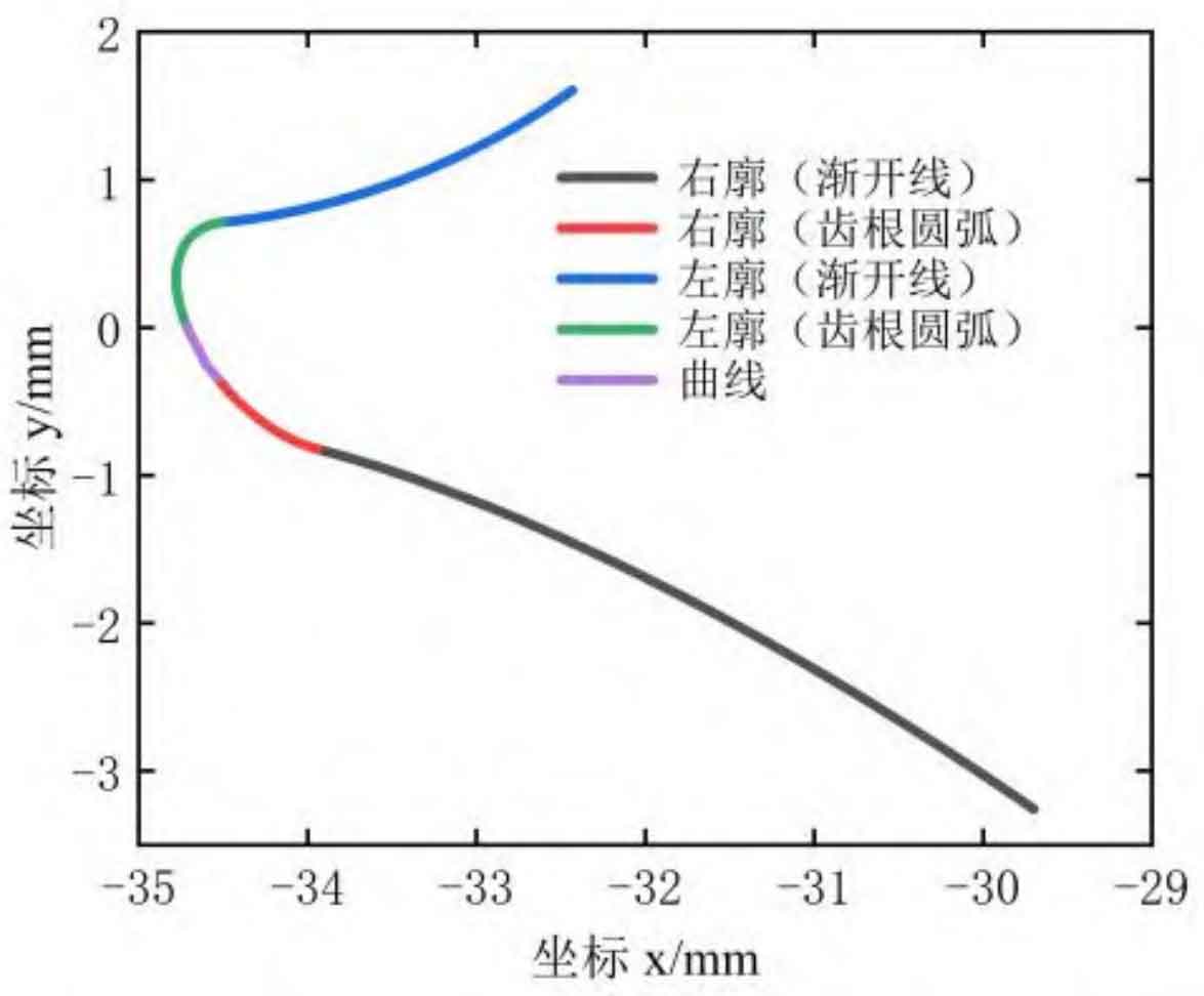
According to the above calculation method of tool rake face profile, the program is written based on MATLAB software to calculate the tool rake face profile. Results as shown in Figure 1, due to the processing time difference between the left and right tooth profiles of the cylindrical gear end face, the contact points of the left and right tooth profiles are asymmetrically arranged, and the profile of the left and right rake surfaces is discontinuous. Therefore, in order to ensure no interference during processing, the designed tool rake surfaces need to smoothly connect the left and right profiles to form a complete tool profile.
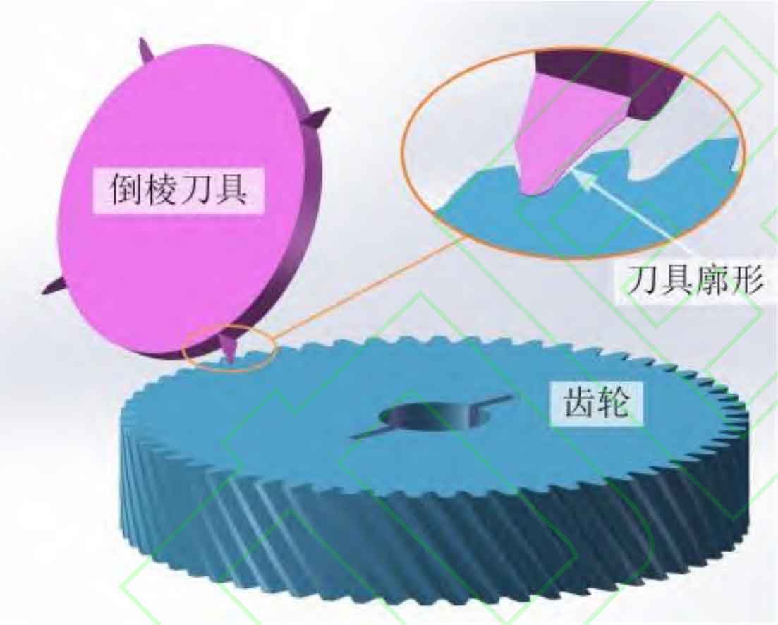
Complete the three-dimensional modeling of cylindrical gear and tool based on SolidWorks, establish the chamfering cutting simulation model (shown in Figure 2) according to the coordination of tool installation pose parameters, and write the simulation motion program to verify the correctness of chamfering motion.
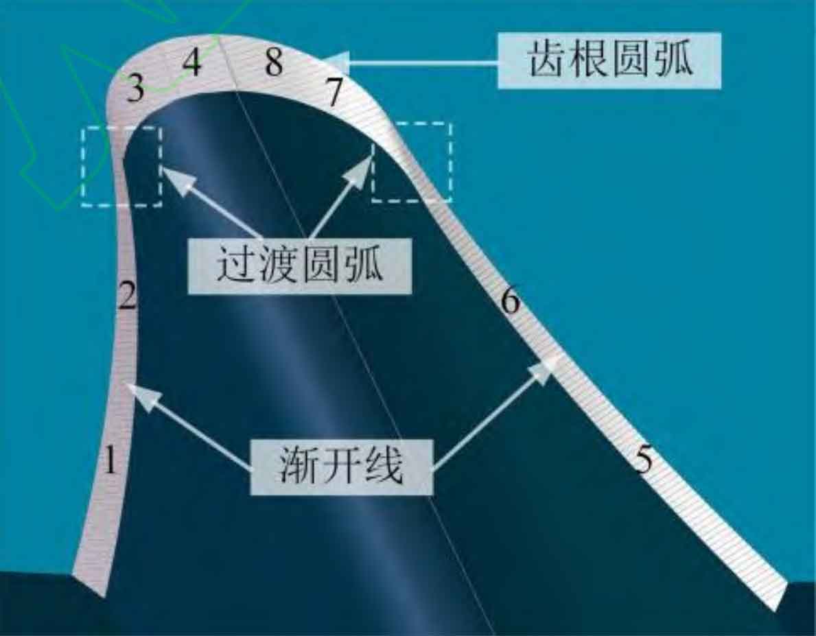
The simulation results of chamfering cutting are shown in Figure 3. From the simulation results, the designed hobbing chamfering tool can process and form an accurate chamfering shape of cylindrical gear tooth profile. Set the chamfering thickness as 0.17mm (the allowable error range is 0.01mm), the chamfering width as 0.2mm (the allowable error range is 0.01mm), and the chamfering angle as 50 ° (the allowable error range is 0.5 °). Select a series of position points on the end tooth profile of the cylindrical gear as the chamfering effect evaluation points to analyze the effect of hobbing chamfering. Select 8 position points on the cylindrical gear profile except the transition arc (as shown in the serial number of Fig. 3), and select 2 evaluation points on the involute part and tooth root arc part of the left and right tooth profiles of the tooth groove respectively. The measurement results are shown in Table 4 below. The analysis and measurement results show that the maximum error of the chamfering thickness of the whole tooth profile is 0.0047mm, the maximum error of the chamfering width is 0.0061mm, and the maximum error of the chamfering angle at the tooth root of the cylindrical gear is 0.2 °. The results are within the allowable error range, which shows that the chamfering effect of the whole tooth profile is consistent; The maximum error of the chamfering thickness at the symmetrical position of the left and right tooth profiles is 0.0031mm, the maximum error of the chamfering width at the symmetrical position is 0.0016mm, and the maximum error of the chamfering angle at the tooth root of the cylindrical gear is 0.1 °. The results are within the allowable error range, indicating that the chamfering effect of the left and right tooth profiles has good symmetry.
| Location | Serial number | Chamfer thickness a (mm) | Chamfering width b (mm) | Chamfer angle (°) |
| Involute part of left tooth profile | 1 | 0.1695 | 0.1988 | / |
| Involute part of left tooth profile | 2 | 0.1684 | 0.1976 | / |
| root part of Left tooth profile | 3 | 0.1719 | 0.2038 | 49.8 |
| root part of Left tooth profile | 4 | 0.1722 | 0.2061 | 50.1 |
| Involute part of right tooth profile | 5 | 0.1679 | 0.1992 | / |
| Involute part of right tooth profile | 6 | 0.1653 | 0.1974 | / |
| root part of right tooth profile | 7 | 0.1701 | 0.2022 | 49.9 |
| root part of right tooth profile | 8 | 0.1712 | 0.2055 | 50.2 |
Compare and analyze the left and right tooth profiles of the simulation results. Because the involute profile of the cylindrical gear and the tooth root profile of the cylindrical gear are connected by the transition arc, the transition arc has uneven chamfering effect due to large curvature change (as shown in Fig. 4), in which the chamfering width is quite different. The tool profile optimization method in this local area will be further studied in the future.
