
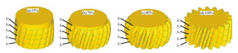
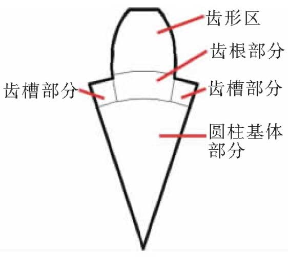
In order to understand the deformation and flow rules of metal in different positions of blank during forming, five sections are evenly intercepted from bottom to top along the direction of tooth width, which are marked as h1, h2, h3, H4 and H5 respectively. The corresponding gear section distribution position with different reduction of punch is shown in Figure 1.Because cylindrical helical gear is a rotationally symmetrical part, the filling law of each tooth is consistent. In this paper, one of the teeth is selected for specific analysis, and the single tooth is divided into four parts: cylindrical base, alveolus, root and tooth shape according to the force condition, as shown in Figure 2.
In this paper, concentric and equidistant circular grid streamlines are drawn on five selected sections by using flow-ne function of Deform-3D finite element simulation software.The shape of these circular mesh streamlines changes with the flow of the billet metal, which can reflect the radial flow law of the billet metal.Figure 2 shows the streamline variation regularity of a circular grid with 5 cross sections under different die depressurizations.
As shown in Figure 2, when the amount of punch press-down is 35%, the streamlines of the circular mesh in the cylindrical base of each section are evenly distributed, the distance between the streamlines remains unchanged, and the meshes of the toothed root and the toothed part are streamlined towards the toothed root of the cavity.When the amount of punch press-down is 70%, the mesh streamlines of cylindrical base parts of each section are evenly distributed, and the mesh spacing on sections h2, H3 and H4 increases slightly; the mesh streamlines of tooth roots and toothed parts continue to bend towards the tooth roots of the cavity, and the spacing increases, thus the degree of bending increases; while the mesh streamlines of part of the toothed groove bend towards the recesses of the base parts under the action of the top of the toothed part of the concaveWhen the amount of punch press-down is 80%, the streamlines of the cylindrical base part of each section are evenly distributed, and the mesh spacing on sections h2, H3 and H4 increases slightly. The mesh streamlines of the tooth roots and the toothed parts continue to bend towards the toothed roots of the cavity, the spacing increases and the degree of bending increases; while the mesh streamlines of the grooved parts still bend towards the recesses of the base part under the action of the top of the toothed part of the concave die.When the punch press-down is 100%, the change rule of mesh streamline is similar to that of 80%, but the bending degree of tooth shape and root part is more serious.
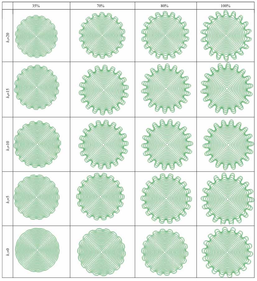
In conclusion, during the whole forming process, the metal of cylindrical base is compressed downwards by the convex die and flows toward the root of the concave die, so the spacing of the mesh streamlines increases; in addition, the circumferential force of this part of metal is uniform, so the circumferential distribution of the mesh streamlines is uniform.Metals in the cylindrical base part flow radially into the groove part, and then the mesh streamline spacing in the groove part decreases due to the obstruction of the top of the concave die.According to the law of minimum resistance, the metal in the root part and the tooth-shaped part flows radially to the top of the concave die. The metal near the tooth profile of the concave die is greatly affected by friction, flows slowly and the bending degree of the mesh streamline is small. The metal far away from the tooth profile of the concave die is less affected by friction, flows quickly and the bending degree of the mesh streamline is large.
In order to study the axial and radial material flow laws of the toothed part in detail, a section is selected in the toothed part and a grid line is drawn on the section to study the axial and radial metal flow as shown in Figure 6.According to the deformation characteristics of the grid, the section is divided into 3 characteristic areas.Zone A is the part where the deformed blank does not enter the cavity of the concave die and is in direct contact with the convex die, Zone B is the part where the upsetting deformation takes place and Zone C is the part where the deformed blank enters the toothed area of the concave die.
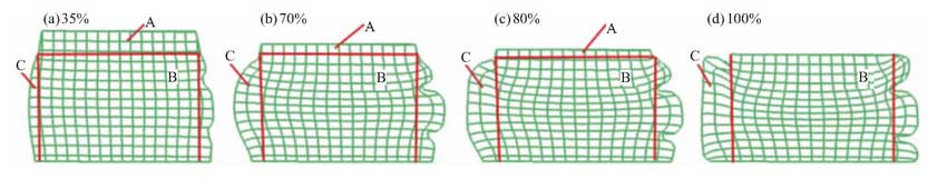
As can be seen from Figure 3, the shape of the mesh in area A has hardly changed and the area in area A decreases as the amount of punch press down increases.Zone B is subjected to axial extrusion of material and base plate in Zone A. The axial mesh streamline bends towards the toothed part and the closer it is to the toothed part, the greater the bending degree of the axial mesh streamline and the greater the distance between the middle parts of the same axial mesh streamline. The transverse mesh streamline bends from the upper and lower ends to the centre part with a reduced distance and is closer to the centre part.The greater the bending, the smaller the spacing.Material in zone C is extruded radially by zone B and friction of concave profile, and extruded circumferentially by concave profile. When the degree of deformation is less than 80%, the axial mesh streamline bends towards the tooth root of the cavity. As the degree of deformation increases, the degree of bending increases and the mesh spacing increases. In addition, both the axial and transverse mesh streamlines increase with the degree of deformation.Increasing bending towards both ends of the tooth increases the spacing between the axial grids, increasing the spacing between the transverse grids in the middle of the tooth and decreasing the spacing between the two ends of the tooth.In the final stage of forming, the transverse grid in area B still bends from both ends to the middle with a slight decrease in spacing, while the streamline of the axial grid bends towards the tooth root of the cavity with little change in spacing; the streamline of the axial and transverse grid in area C bends towards the corner of both ends of the toothed, and the streamline spacing in the middle part of the toothed basically does not change, while the axial grid spacing in the upper and lower corners increases and the transverse grid increases.The spacing decreases.