
In modern automotive engineering, electric power steering (EPS) systems have become increasingly prevalent due to their advantages over traditional hydraulic systems, such as improved fuel economy, reduced weight, and enhanced controllability. The core mechanical component that enables torque amplification and direction change in many EPS architectures is the worm gear pair. In this paper, I present a comprehensive design and calculation methodology for an EPS system tailored to a specific passenger vehicle, with a particular focus on the worm gears used in the reduction mechanism. I systematically derive system matching parameters, design the worm gear pair, perform nonlinear contact finite element analysis on the worm gears, and validate the design through prototype testing. The entire process emphasizes the critical role of worm gears in achieving the required assist torque while ensuring reliability and compactness.
System Parameter Matching for EPS
I began by establishing the required assist torque based on the target vehicle’s parameters. The vehicle has a curb mass of 1420 kg, a front axle load of 950 kg, and a maximum speed of 180 km/h. Using a torque-angle sensor, the maximum steering resistance torque at full load was measured to be 28 N·m. Since a driver typically expects a hand torque of 5–6 N·m, the EPS system must provide an additional assist torque of approximately 23 N·m. Considering an overall system efficiency of 80% (including mechanical losses in the worm gears and other transmission components), the required motor torque and reduction ratio can be determined.
I selected a 170 W brushed DC motor with a rated current of 30 A and a rated torque of 1.6 N·m. The reduction ratio necessary to meet the 23 N·m assist requirement is calculated as:
$$
i = \frac{T_{\text{assist}}}{T_{\text{motor}} \cdot \eta} = \frac{23}{1.6 \times 0.8} = 17.97 \approx 18.5
$$
Thus, a reduction ratio of 18.5:1 was chosen. The EPS system is a column-assist type (P-EPS) with an IP67 protection rating. A contact-type potentiometric torque sensor with 5 V supply is used, and the ECU is designed to output a maximum current of 35 A. No electromagnetic clutch is employed to reduce cost and failure rate. The matching parameters are summarized in the table below.
| Component | Specification |
|---|---|
| Brushed motor | 170 W / 30 A rated, 1.6 N·m rated torque |
| Torque sensor | Contact-type potentiometric, 5 V supply |
| ECU | Maximum output current 35 A |
| Reduction mechanism | 18.5:1, worm gear pair |
| Protection class | IP67 |
Reduction Mechanism Design with Worm Gears
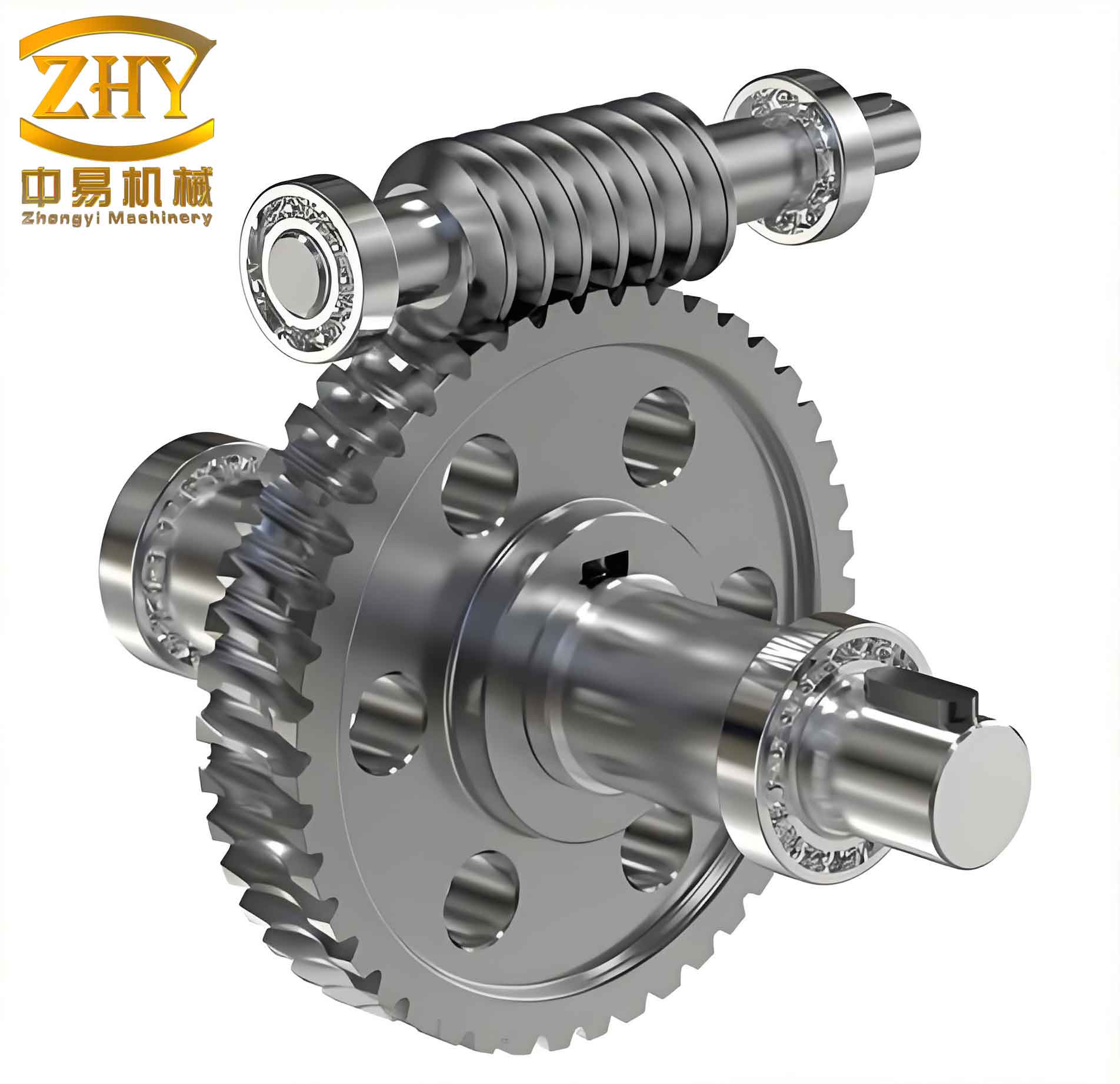
The reduction mechanism is realized through a worm gear pair, which is essential for achieving the required torque amplification while maintaining a compact layout. The worm gears must be designed to be non-self-locking in the reverse direction, meaning the worm wheel can drive the worm shaft during manual steering or when the motor is inactive. This requires a large lead angle on the worm. I selected a lead angle of 19°17′ to satisfy this condition.
For the worm wheel, the outer tooth ring is made of nylon PA66 to reduce friction and provide self-lubrication, while the inner hub is made of 45 steel. The worm itself is made of 40Cr steel with quenching and tempering treatment. The basic parameters of the worm gears are given in the following table.
| Parameter | Worm | Worm Wheel |
|---|---|---|
| Module | 2.15 | 2.15 (end face module) |
| Lead angle | 19°17′ | 19°17′ (helix angle) |
| Number of starts / teeth | 2 (right-hand) | 37 (right-hand) |
| Center distance (mm) | 46.5 | 46.5 |
| Addendum modification coefficient | — | 0.269 |
| Tooth form tolerance (mm) | — | 0.008 |
| Axial pitch cumulative deviation (mm) | ±0.007 | — |
The worm gears are designed to operate with a high degree of precision to minimize backlash and noise. The combination of a large lead angle and a polymeric worm wheel material ensures low friction and good wear resistance, which are critical for long-term durability in automotive applications. In the following section, I perform a detailed nonlinear contact analysis of this worm gear pair to verify its structural integrity.
Nonlinear Contact Finite Element Analysis of Worm Gears
Because the worm gears experience intermittent contact and separation during meshing, a linear static analysis is inadequate. I employed a nonlinear contact finite element method using a penalty formulation to simulate the interaction between the worm and worm wheel. The goal is to evaluate the contact stresses and deformations under the rated torque condition.
Finite Element Model
I created a solid model of the worm gears in CAD software and imported it into the FEA environment. Only the worm and worm wheel were modeled; the bearings and housing were replaced by appropriate boundary conditions. To reduce computational cost, a half-model of the worm wheel was used, exploiting symmetry. The mesh consisted of hexahedral elements for better accuracy, with local refinement at the contact regions. The model is shown below (schematic illustration).
Material Properties
The material properties used in the simulation are listed below. The worm wheel’s outer tooth ring (PA66) is assumed to be isotropic, while the steel components are treated as linear elastic.
| Component | Material | Elastic Modulus (MPa) | Poisson’s Ratio | Allowable Stress (MPa) |
|---|---|---|---|---|
| Worm wheel outer teeth | PA66 | 11400 | 0.35 | 95 |
| Worm wheel hub | 45 steel | 210000 | 0.28 | — |
| Worm | 40Cr | 206000 | 0.3 | 940 |
Boundary Conditions
I applied the following constraints to accurately represent the operating conditions of the worm gears:
- All degrees of freedom on the inner diameter of the worm wheel hub were fixed, simulating the connection to the steering column.
- The worm was allowed to rotate only about its own axis (X-direction), with all other translations and rotations constrained, representing the support of two bearings.
- Contact pairs were defined between the worm and worm wheel tooth surfaces. The worm wheel surface was designated as the contact surface (CONTA173), and the worm surface as the target surface (TARGE170). A penalty formulation with a contact stiffness scaling factor of 0.1 was used. The coefficient of friction between the worm gears was set to 0.07.
Load Case
The motor provides a rated torque of 1.6 N·m at the worm input. In the FEA, torque cannot be applied directly, so I converted it into equivalent tangential forces. The pitch radius of the worm at the input end is 4.75 mm. Ten equal forces were applied to nodes on the worm shaft end to represent the torque:
$$
F = \frac{T}{r \cdot n} = \frac{1.6}{0.00475 \times 10} = 33.7 \text{ N}
$$
These forces act in the tangential direction to simulate the motor torque. The worm wheel is assumed to be locked (fixed inner diameter) representing the reaction from the steering resistance.
Results and Discussion
A structural static analysis was performed, extracting von Mises stress, total deformation, and contact status. The simulation revealed that the maximum equivalent stress in the worm gear pair is approximately 53 MPa, occurring on the worm wheel tooth flank at the area of contact. This stress level is well below the allowable 95 MPa for PA66, indicating a safe design. The maximum deformation of 0.2 mm occurs at the load application point on the worm shaft, which is consistent with the expected elastic deflection. The stress distribution on the worm gears shows a concentrated region near the line of contact, which is typical for worm gear meshing. Because the worm wheel is fixed in this analysis, the actual stress in real operating conditions (where the wheel rotates against variable resistance) would be equal or lower, confirming the adequacy of the design.
The nonlinear contact analysis successfully captured the complex interaction between the worm gears, including the gradual engagement and disengagement of teeth. The contact pressure distribution is smooth, and no penetration issues were observed. This demonstrates that the worm gears can safely transmit the rated torque without exceeding material limits.
Prototype Testing and Vehicle Validation
After completing the design and analysis of the worm gears, I built a prototype EPS system. The assembly passed a durability test on a bench fixture, and functional tests confirmed that all parameters met specifications. Subsequently, a test vehicle equipped with this EPS system was subjected to a 10 km road test, including slalom maneuvers to evaluate assist performance and driver feel. The assist curve sampled during the test is shown qualitatively below.
The test results indicated that the EPS system provided smooth, proportional assist that increased at low speeds and decreased at higher speeds, as intended. The hand torque required by the driver remained within the 5–6 N·m range even during parking maneuvers, while high-speed stability was maintained. No abnormal noise or vibration from the worm gears was observed. The durability test further confirmed that the worm gears showed negligible wear after extended cycling.
Conclusion
In this work, I systematically designed an electric power steering system for a specific passenger vehicle, with a strong emphasis on the worm gears that form the reduction mechanism. Through parameter matching, I determined that a reduction ratio of 18.5:1 is required to deliver the necessary 23 N·m assist torque. The worm gears were designed with a large lead angle of 19°17′ to ensure non-self-locking behavior, and materials were selected to balance strength and low friction. Nonlinear contact finite element analysis of the worm gears revealed a maximum stress of 53 MPa, well within the allowable limits. Prototype testing and vehicle road tests validated the design, showing excellent assist performance and durability. The success of this project reinforces the importance of careful worm gear design in modern EPS applications, where reliability, efficiency, and compactness are paramount.