
Spur bevel gears are important mechanical components, and their main function is similar to that of general cylindrical gears, through the mutual
Meshing is used to transmit torque. Compared to spur gears, bevel gears have several advantages: ① the shaft of the bevel gear can be installed at any angle between 0° and 90°; ② bevel gears operate more smoothly and transmit larger torques than spur gears; ③ the module of spur bevel gears varies from one end to the other end of the full tooth width. Spur bevel gears are also used in pairs. When testing gear components, some testing parameters require testing of individual gears, such as tooth height, common normal length, chordal tooth thickness, etc. However, there are other parameters that we must test when the gears are paired and meshed with each other, such as detection of taper angle, shaft angle, contact spot, tooth flank clearance, and tooth tip clearance. If the paired gears are assembled on the product without being checked for pairing, once the tooth flank meshing problem is discovered, it will be more cumbersome to disassemble them because the general spur bevel gear and the supporting transmission shaft are assembled by interference fit or transition fit through hot or cold installation, which is relatively compact and difficult to disassemble twice. Therefore, it requires us to design a tooling for bevel gear meshing to check the testing elements in advance under the condition of gear meshing.
Product Introduction
One of the main domestic manufacturers of rubber and plastic machinery, including internal mixer, twin screw extruder, flat vulcanizer, tire vulcanizer, etc. Here we study the main transmission components on the twin screw extruder, synchronous bevel gears, specifically model 416 single-mounted double-bevel twin screw extruder. It belongs to the equal-top-clearance straight bevel gear with 48 teeth, pressure angle of 20°, conical angle of 7°, large end module of 20 mm, design normal length of 338.14 mm, and assembly side clearance of 0.5 mm. In the actual assembly process, we often encounter such situations that after the assembly of two cooperating bevel gears, when using a feeler gauge to check the side clearance between the meshing and non-meshing surfaces, it is found that the side clearance of the large end of the bevel gear is different from that of the small end of the bevel gear, and the difference is relatively large. Therefore, when the gears are meshed for transmission, they cannot fully contact in the direction of tooth width, and the contact patch is smaller than the design requirement. This will cause different wear on the tooth surfaces of the cooperating bevel gears, exacerbating the wear on the contact parts, while leaving non-contact areas undamaged or slightly worn, seriously affecting the transmission effect and service life of the bevel gear. For this problem that affects assembly quality, we cannot eliminate all non-conforming items in the assembly process by relying solely on quality inspection of individual bevel gears. Moreover, once a non-conforming bevel gear is installed on a product, it is relatively time-consuming and laborious for assembly workers to remove it, and it is easy to damage the self-aligning roller bearing or transmission shaft. This is why we design a bevel gear meshing fixture.
Fixture structure
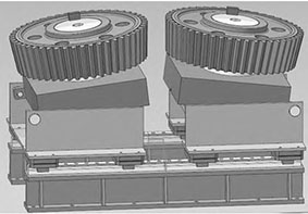
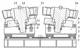
The tooling for meshing of bevel gears is shown in the figure
Tooling operation steps
(1)Before installing the bevel gear, restore the fixed block to a horizontal state.
(2) Install the bevel gear (No. 16). It is important to note that the mating surface of the bevel gear inner hole needs to be coated with lubricant before installation; in addition, as a check
When measuring the tooling, we need to change the fit size between the outer diameter of the mounting shaft and the inner diameter of the bevel gear from the interference or transition fit designed in the drawing to a clearance fit, and appropriately reduce the outer diameter of the mounting shaft. These steps will help us smoothly install and remove the bevel gear.
(3) Install the key (serial number 15) to secure the bevel gear and the mounting shaft, preventing the individual bevel gear from rotating freely around the mounting shaft.
(4) Check the round nut (No. 10) on the end of the pre-tightened installation shaft to prevent the inner and outer rings of the self-aligning roller bearing used for positioning under the tooling from loosening.
(5) According to the design of the bevel gear drawing, the bevel angle is achieved by adjusting the support bolt (No. 9) to drive the fixed block (No. 7) to rotate around the pin shaft (No. 5). When the bevel angle is 0°, it is possible to pair check the spur gear.
(6) Move the bracket (No. 6) along the guide rail to ensure smooth meshing of the two bevel gears.
(7) Lock the locking slider (No. 3) to secure the bracket and prevent lateral displacement of the bracket along the guide rail (2).
(8) By installing the hexagonal wrench hole on the end face of the shaft (No. 14), two meshing gears can easily rotate around the shaft manually.
Main parameters and application scope
(1) Overall dimensions: 2000 mm×1020 mm×1300 mm
(2) Application range of tooling: spur gear, bevel gear
(3) adjustable cone angle range of tooling: 0~20°
(4) Diameter range of gear: Ф800~Ф1 200
(5) Maximum gear weight: 5 t/piece
Analysis of meshing detection of bevel gear
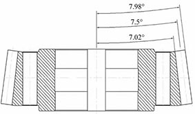
The meshing of straight bevel gears is mainly affected by two parameters, one is the pitch and the other is the tooth profile It is the cone angle. The cone pitch determines the position of a pair of meshing bevel gears on the rotating shaft, just like the center distance parameter of cylindrical gears The same is that the centers of cylindrical gears are parallel to each other, while the centers of bevel gears form a certain angle. The pitch is a parameter value given by design, and we can determine it through Adjusting the pitch of the cone gears can be used to adjust the side clearance of the meshing tooth surfaces. Moving towards the smaller end of the cone gears will decrease the side clearance, while moving towards the larger end will increase the side clearance. However, this is only Only when the taper angles of the two bevel gears are consistent can they adjust the side clearance of the gear mesh. If the taper angles of the paired bevel gears are not consistent The effect of adjusting the tooth flank clearance by adjusting the cone pitch will disappear. The sub-cone angle is a parameter that reflects the angle between the center of the bevel gear and the straight line of the index circle. It directly determines the size of the contact patch area on the tooth surfaces of two known bevel gears, thus determining the quality of power transmission through the meshing surface. Practice has shown that there are four situations that occur during the assembly process of bevel gears: First, in the ideal state of bevel gear meshing, as shown in Figure 4 The straight lines of the two bevel gears’ indexing circles will coincide, the tooth flank backlash is completely eliminated, and the tooth flank meshing surface and non-meshing surface backlash are both zero. This situation is common in practical applications In practical applications, considering the existence of machining errors and the tendency of meshing teeth to get stuck under zero backlash conditions, this situation is rarely encountered.
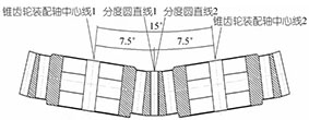
In the parallel state, the bevel gear meshes. It refers to the fact that the back and front side clearances of the gear meshing surface are both zero, rather than leaving a certain amount of side clearance on the meshing surface and equalizing the side clearance values of the bevel gears along the tooth width direction. The specific side clearance value is determined by the designer based on the processing accuracy level and usage conditions of the gear itself. If the measured side clearance value of the actual paired bevel gears is larger than the design requirement, it means that the two gears need to move a certain distance in the axial direction; on the other hand, if the measured side clearance value is smaller than the design requirement, the two gears need to move a certain distance outward along the axial direction. This distance adjustment is usually achieved by adjusting the width of two distance sets installed at the front and rear positions of the bevel gears.
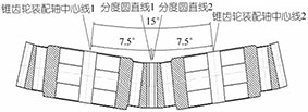
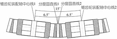
In the case of a large cone angle deviation, the meshing state of the bevel gear is shown. In this state, the side clearance value of the small end of the bevel gear measured with a feeler gauge is smaller than that of the large end of the bevel gear, and the side clearance values of the meshing and non-meshing surfaces of the large end are not zero. This indicates that the meshing state of such paired bevel gears is far from ideal, and only a portion of the tooth surfaces on the small end of the bevel gear can effectively transmit power, which will inevitably lead to increased wear on the contact part of the tooth surface, greatly reducing the service life of the bevel gear. During operation, irregular meshing noise may occur. In this case, the bevel gear can only be scrapped directly, or for some cases where the side clearance value deviation is not significant, it can be manually repaired and then used as a defective product for downgrading. In the case of a small cone angle deviation, the meshing state of the bevel gear is shown. In this state, the side clearance value of the small end of the bevel gear measured with a feeler gauge is larger than that of the large end of the bevel gear, and the side clearance values of the meshing and non-meshing surfaces of the small end are not zero. This indicates that only a portion of the tooth surfaces on the large end of the bevel gear are in normal contact, and the handling method can also refer to the third method for handling.
Summary
It is very necessary to conduct a gear pairing engagement inspection, and its results cannot directly reflect whether a single quality requirement is qualified or not during the gear processing process No, it is only an inspection of the assembly quality of gear meshing. The detection of bevel gear meshing is mainly affected by the taper of the gear teeth, in addition to the direct influence of the tooth profile itself The influence of the distance and the taper angle. The tooth profile can be checked individually using a tooth profile template to eliminate errors; the taper angle is a fixed value given by the design, once determined it cannot be changed It does not have any effect on the bevel gear itself; the only remaining determining factor is the conic angle. Our reference circle is a virtual circle, In practice, it is difficult to measure its specific dimensions, let alone the conical angle based on the index circle. This tool can not only help us Before formal assembly, the tooth flank clearance of the two bevel gears can be detected, and the pitch of the bevel gears can be calculated and adjusted based on the actual measured lateral clearance value to achieve the desired gear meshing state.