
In the pursuit of superior surface finish and geometric accuracy in gear manufacturing, the integration of ultrasonic vibration-assisted machining has emerged as a transformative technology. Ultrasonic-assisted gear honing represents a significant advancement over conventional honing processes. By superimposing high-frequency, low-amplitude vibrations onto the honing tool’s motion, the effective cutting speed and material removal capability of the abrasive grains are dramatically enhanced. This leads to improved surface integrity, reduced machining forces, and extended tool life. From the perspectives of processing efficiency, final quality, and economic viability, ultrasonic gear honing can deliver exceptionally satisfactory results. The core of this technology lies in the design of an effective vibration system that can reliably transmit ultrasonic energy to the gear workpiece.
The vibration system for ultrasonic gear honing primarily consists of an ultrasonic transducer, a horn (or amplitude transformer), and the gear itself. The gear, functioning as the tool or workpiece, has specific requirements for its vibration frequency, mode shape, and amplitude. However, the structural dimensions of a gear are typically dictated by its functional application and are not variable design parameters. Furthermore, the frequency tuning range of practical ultrasonic generators is limited. Consequently, it is challenging to guarantee that the resonant frequency of a gear with arbitrary dimensions falls within the operational range of the ultrasonic vibration system. This fundamental mismatch renders the traditional “full resonance” theory, where every component is individually tuned to the same frequency, inadequate for system design.
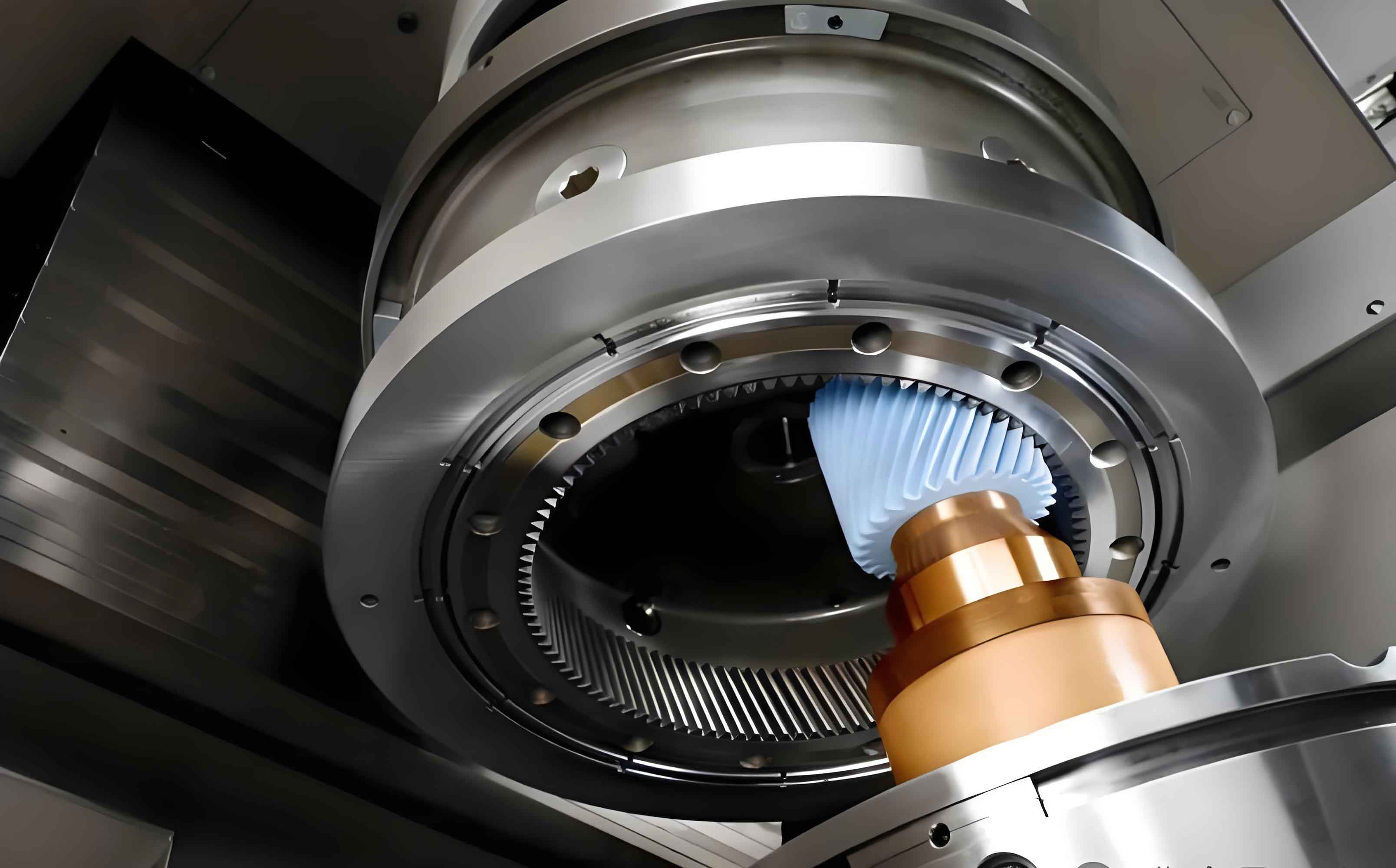
Compared to typical tool heads in ultrasonic machining, a gear possesses considerable mass and size, making its dynamic influence non-negligible. Yet, it is also unsuitable for design using simple mass substitution methods or partial resonance theory. This necessitates a novel design methodology—the non-resonance theory. This approach treats the combined system of the horn and the gear as a single, integrated vibratory unit. Instead of forcing the gear to resonate at a predetermined frequency, the system’s overall resonant frequency is achieved by strategically designing the horn’s geometry to compensate for the gear’s dynamic characteristics. For effective gear honing, the gear must undergo axisymmetric transverse bending vibration (with a nodal diameter number of zero) to ensure uniform material removal and high surface quality. While prior analyses often simplified the gear as a thin annular plate, the error of such approximations increases with the gear’s thickness-to-diameter ratio. Therefore, a more accurate model based on thick-plate theory is essential for designing high-performance ultrasonic gear honing systems.
This article focuses on the dynamic characteristics of a novel ultrasonic transformer specifically designed for gear honing applications. The transformer comprises a longitudinally vibrating conical horn with a central bore and a transversely bending thick annular plate, which represents a simplified model of the gear. By applying non-resonance theory, we establish a comprehensive dynamic model, derive the system’s frequency equation, and investigate the influence of key geometric parameters. Finite element analysis and experimental validation are employed to verify the theoretical predictions, providing a robust foundation for the practical design of such systems.
1. Structural Configuration and Mathematical Modeling of the Novel Transformer
1.1 Structural Configuration
The proposed novel transformer is formed by connecting a conical horn with a central bore to a thick annular plate, as illustrated schematically. The conical horn is characterized by its large-end radius $R_1$, small-end radius $R_2$, length $L_1$, and central bore radius $R_3$. The gear is modeled as an annular plate of constant thickness $h$ (equal to the gear width), with an inner radius $R_5$ and an outer radius $R_4$, where $R_4$ corresponds to the gear’s pitch circle diameter. The left end of the horn is connected to the output surface of the ultrasonic transducer (not shown), which is considered purely as a vibration source. The annular plate is mounted onto a mandrel at the horn’s small end and secured with a nut. The nut’s dimensions are negligible compared to the gear and are omitted from the analysis. When the gear (annular plate) and the horn vibrate in concert, their dynamic characteristics couple, altering the system’s overall behavior. The central bore in the horn is introduced to accommodate the mounting mandrel, especially relevant for gears with large central holes. The system’s resonant frequency and vibration mode can therefore be tuned by adjusting the horn’s dimensions ($L_1$, $R_1$, $R_2$, $R_3$).
1.2 Mathematical Formulation
The dynamic analysis requires governing equations for both components. For the thick annular plate undergoing axisymmetric transverse bending vibration, Mindlin’s plate theory is applied. This theory accounts for transverse shear deformation and rotary inertia, making it accurate for plates with thickness-to-diameter ratios in the range of approximately 1/5 to 1/2, which encompasses typical gears. Under axisymmetric conditions with no tangential strain, the displacement and internal force functions in polar coordinates $(r)$ are given by:
Rotation:
$$ \psi_r = \delta_1(1-\sigma_1)[A_1 J_1(\delta_1 r) + B_1 N_1(\delta_1 r)] + \delta_2(1-\sigma_2)[A_2 J_1(\delta_2 r) + B_2 N_1(\delta_2 r)] $$
Transverse Displacement:
$$ u_2(r) = A_1 J_0(\delta_1 r) + B_1 N_0(\delta_1 r) + A_2 J_0(\delta_2 r) + B_2 N_0(\delta_2 r) $$
Bending Moment:
$$ M_r = \sum_{i=1}^{2} A_i (\sigma_i – 1) \left[ J_0”(\delta_i r) + \frac{\upsilon}{r} J_0′(\delta_i r) \right] + \sum_{i=1}^{2} B_i (\sigma_i – 1) \left[ N_0”(\delta_i r) + \frac{\upsilon}{r} N_0′(\delta_i r) \right] $$
Shear Force:
$$ Q_r = k^2 G h \sum_{i=1}^{2} \left[ A_i \sigma_i J_0′(\delta_i r) + B_i \sigma_i N_0′(\delta_i r) \right] $$
where:
- $u_2(r)$ is the transverse displacement of the annular plate.
- $\psi_r$ is the rotation of the plate cross-section.
- $Q_r$ and $M_r$ are the shear force and bending moment, respectively.
- $J_n$ and $N_n$ are the Bessel and Neumann functions of order $n$.
- $A_1, A_2, B_1, B_2$ are unknown constants determined by boundary conditions.
- The parameters $\sigma_i$, $\delta_i$, $R$, $S$, and $\delta_0$ are defined as:
$$ \sigma_i = \frac{\delta_i^2}{R \delta_0^4 – S^{-1}}, \quad i=1,2 $$
$$ \delta_1^2 = \frac{1}{2} \delta_0^4 \left\{ R + S + \left[ (R-S)^2 + \frac{4}{\delta_0^4} \right]^{1/2} \right\} $$
$$ \delta_2^2 = \frac{1}{2} \delta_0^4 \left\{ R + S – \left[ (R-S)^2 + \frac{4}{\delta_0^4} \right]^{1/2} \right\} $$
$$ R = \frac{h^2}{12}, \quad S = \frac{D}{k^2 G h}, \quad \delta_0^4 = \frac{\rho \omega^2 h}{D} $$ - $k^2 = \pi^2/12$ is the shear correction factor.
- $\rho$, $\omega$, $D$, $G$, $E$, and $\upsilon$ are the material density, angular frequency, flexural rigidity ($D=Eh^3/[12(1-\upsilon^2)]$), shear modulus, Young’s modulus, and Poisson’s ratio, respectively.
For the longitudinally vibrating conical horn with a central bore, the one-dimensional wave equation for a variable cross-section bar is used. The displacement function $u_1(x)$ along the horn’s axis (with $x=0$ at the small end connected to the gear and $x=-L_1$ at the large end connected to the transducer) is:
$$ u_1(x) = \frac{1}{R_1 – R_3 – \frac{R_1 – R_2}{L_1} x} \left[ A_5 \cos(k’ x) + A_6 \sin(k’ x) \right] $$
where $k’ = \omega / c$ is the wave number, $c = \sqrt{E/\rho’}$ is the longitudinal wave speed in the horn material (density $\rho’$), and $A_5$, $A_6$ are unknown constants.
2. System Frequency Equation and Boundary Conditions
The dynamic characteristics of the coupled transformer system are determined by enforcing compatibility conditions at the interfaces and boundaries. The following boundary conditions are established:
1. Horn Input End ($x = -L_1$): Connected to the transducer, this end is assumed to have a maximum displacement $\xi_0$ and is a displacement antinode (zero stress).
$$ u_1(x)\big|_{x=-L_1} = \xi_0, \quad \frac{\partial u_1(x)}{\partial x}\bigg|_{x=-L_1} = 0 $$
2. Horn-Annular Plate Interface ($x=0$, $r=R_2$): The interface requires continuity of displacement and force.
$$ u_1(x)\big|_{x=0} = u_2(r)\big|_{r=R_2} $$
$$ E \frac{\partial u_1(x)}{\partial x}\bigg|_{x=0} = G \frac{\partial u_2(r)}{\partial x}\bigg|_{r=R_2} \quad \text{(Equilibrium of longitudinal force in horn and shear force in plate)} $$
3. Annular Plate Inner Boundary ($r=R_5$): This boundary corresponds to the mounting location on the horn’s mandrel. Assuming the connection stiffness is much higher than the plate’s bending stiffness, the slope (rotation) is constrained to zero.
$$ \psi_r(R_5) = 0 \quad \text{or equivalently} \quad u_2′(R_5) = 0 $$
4. Annular Plate Outer Boundary ($r=R_4$): The outer edge of the gear is free.
$$ M_r(R_4) = 0, \quad Q_r(R_4) = 0 $$
Substituting the displacement functions $u_1(x)$ and $u_2(r)$, along with the force expressions, into these six boundary conditions yields a homogeneous linear system of equations with the six unknown constants $A_1, A_2, B_1, B_2, A_5, A_6$. For a non-trivial solution to exist, the determinant of the coefficient matrix must vanish. This condition yields the characteristic frequency equation for the novel transformer system:
$$ \Delta(\omega) =
\begin{vmatrix}
C_{11} & C_{12} & C_{13} & C_{14} & C_{15} & C_{16} \\
C_{21} & C_{22} & C_{23} & C_{24} & C_{25} & C_{26} \\
C_{31} & C_{32} & C_{33} & C_{34} & C_{35} & C_{36} \\
C_{41} & C_{42} & C_{43} & C_{44} & C_{45} & C_{46} \\
C_{51} & C_{52} & C_{53} & C_{54} & C_{55} & C_{56} \\
C_{61} & C_{62} & C_{63} & C_{64} & C_{65} & C_{66} \\
\end{vmatrix} = 0 $$
Equation $\Delta(\omega) = 0$ is a transcendental equation whose roots $\omega_n$ correspond to the system’s resonant frequencies. Solving this equation numerically for a given set of geometric parameters provides the design frequency. Subsequently, the constants $A_i, B_i$ can be found, and the displacement distributions $u_1(x)$ and $u_2(r)$ can be plotted to analyze vibration mode shapes, node locations, and amplitude distributions. This frequency equation is the cornerstone of the non-resonant design methodology for ultrasonic gear honing transformers.
3. Numerical Analysis and Finite Element Verification
To validate the theoretical model and investigate parametric influences, numerical calculations and Finite Element Analysis (FEA) were performed. The material for both horn and annular plate was selected as 45 steel with the following properties: density $\rho = 7.8 \times 10^3$ kg/m³, Poisson’s ratio $\upsilon=0.28$, Young’s modulus $E=2.16 \times 10^{11}$ Pa, and shear modulus $G=8.4 \times 10^{10}$ Pa.
3.1 Parametric Influence on System Resonant Frequency
The influence of key geometric parameters on the system’s first longitudinal-bending resonant frequency was analyzed. Four cases are presented in tables comparing theoretical results ($f_1$) from solving the frequency equation, FEA results ($f_2$), the isolated longitudinal resonant frequency of the bored horn ($f_3$), and the isolated bending frequency of the annular plate ($f_4$). The percent error $\Delta f$ is between $f_1$ and $f_2$.
Table 1: Effect of Annular Plate Thickness ($h$) (Base: $R_1=35$mm, $R_2=8$mm, $L_1=197$mm, $R_3=6$mm, $R_4=60$mm, $R_5=8$mm)
| $h$ (mm) | $h/R_2$ | $f_1$ (kHz) | $f_2$ (kHz) | $f_3$ (kHz) | $f_4$ (kHz) | $\Delta f$ (%) |
|---|---|---|---|---|---|---|
| 10 | 0.40 | 19.676 | 18.960 | 19.000 | 18.517 | 3.78 |
| 11 | 0.44 | 20.072 | 19.304 | 19.000 | 19.719 | 3.98 |
| 12 | 0.48 | 20.737 | 19.892 | 19.000 | 20.743 | 4.25 |
| 13 | 0.52 | 21.470 | 20.475 | 19.000 | 21.952 | 4.86 |
Table 2: Effect of Horn Length ($L_1$) (Base: $R_1=35$mm, $R_2=8$mm, $R_3=6$mm, $R_4=60$mm, $R_5=8$mm, $h=10$mm)
| $L_1$ (mm) | $h/R_2$ | $f_1$ (kHz) | $f_2$ (kHz) | $f_3$ (kHz) | $f_4$ (kHz) | $\Delta f$ (%) |
|---|---|---|---|---|---|---|
| 187 | 0.40 | 11.774 | 11.287 | 16.214 | 18.517 | 4.32 |
| 192 | 0.40 | 16.071 | 15.462 | 18.426 | 18.517 | 3.94 |
| 197 | 0.40 | 19.676 | 18.960 | 19.000 | 18.517 | 3.78 |
| 202 | 0.40 | 22.495 | 21.473 | 27.067 | 18.517 | 4.76 |
Table 3: Effect of Horn Bore Radius ($R_3$) (Base: $R_1=35$mm, $R_2=8$mm, $L_1=197$mm, $R_4=60$mm, $R_5=8$mm, $h=10$mm)
| $R_3$ (mm) | $h/R_2$ | $f_1$ (kHz) | $f_2$ (kHz) | $f_3$ (kHz) | $f_4$ (kHz) | $\Delta f$ (%) |
|---|---|---|---|---|---|---|
| 3 | 0.40 | 11.756 | 11.313 | 19.000 | 22.794 | 3.92 |
| 4 | 0.40 | 15.179 | 14.572 | 19.000 | 21.463 | 4.17 |
| 5 | 0.40 | 17.501 | 16.783 | 19.000 | 19.832 | 4.28 |
| 6 | 0.40 | 19.676 | 18.960 | 19.000 | 18.158 | 3.78 |
| 7 | 0.40 | 19.992 | 19.124 | 19.000 | 16.472 | 4.54 |
| 8 | 0.40 | 20.168 | 19.232 | 19.000 | 15.639 | 4.87 |
Table 4: Effect of Annular Plate Outer Radius ($R_4$) (Base: $R_1=35$mm, $R_2=8$mm, $L_1=197$mm, $R_3=6$mm, $R_5=8$mm, $h=10$mm)
| $R_4$ (mm) | $h/R_2$ | $f_1$ (kHz) | $f_2$ (kHz) | $f_3$ (kHz) | $f_4$ (kHz) | $\Delta f$ (%) |
|---|---|---|---|---|---|---|
| 25 | 0.400 | 19.676 | 18.960 | 19.000 | 15.639 | 3.78 |
| 28 | 0.357 | 14.441 | 13.874 | 19.000 | 13.574 | 4.09 |
| 30 | 0.333 | 13.167 | 12.618 | 19.000 | 11.625 | 4.35 |
| 32 | 0.312 | 10.581 | 10.125 | 19.000 | 10.237 | 4.51 |
| 34 | 0.294 | 8.666 | 8.278 | 19.000 | 8.975 | 4.69 |
Key Observations from Parametric Studies:
- Plate Thickness (Table 1): System frequency $f_2$ increases with $h$. The horn’s isolated frequency $f_3$ is constant, while the plate’s isolated frequency $f_4$ increases. The system frequency $f_2$ is distinct from both $f_3$ and $f_4$, confirming the non-resonant coupling.
- Horn Length (Table 2): System frequency $f_2$ is highly sensitive to $L_1$ and changes significantly, again differing from both component frequencies.
- Horn Bore Radius (Table 3): Increasing $R_3$ (making the horn more “hollow”) generally increases the system frequency $f_2$, providing a tuning parameter.
- Plate Outer Radius (Table 4): Increasing $R_4$ (larger gear diameter) decreases the system frequency $f_2$, as expected from increased inertia.
- Agreement: The theoretical ($f_1$) and FEA ($f_2$) results show consistent trends and agreement within ~5%, validating the analytical model.
3.2 Detailed Finite Element Analysis of a Designed Transformer
Using the frequency equation, a specific transformer was designed for a target frequency near 19 kHz. The parameters are: $R_1=35$mm, $R_2=8$mm, $L_1=197$mm, $R_3=6$mm, $R_4=60$mm, $R_5=8$mm, $h=18$mm. A 3D finite element model was built and meshed with SOLID45 elements. A modal analysis using the Block Lanczos method was performed with the inner rim of the annular plate ($r=R_5$) radially constrained to simulate the mounting.
The FEA results identified a dominant axisymmetric bending mode at 18.96 kHz, closely matching the theoretical target. This mode exhibited pure longitudinal vibration in the horn coupled with axisymmetric transverse bending in the annular plate—the desired mode for effective gear honing. The displacement nephogram clearly shows this coupled behavior. The axial displacement distribution along the horn extracted from FEA shows a node location approximately 65 mm from the large end, which aligns with theoretical predictions for a longitudinally vibrating horn of this profile. Similarly, the radial distribution of transverse displacement on the annular plate from FEA matches the characteristic shape predicted by the thick-plate theory solution, with the maximum amplitude not necessarily at the outer edge.
4. Experimental Validation
To further validate the theoretical and numerical findings, a prototype transformer was manufactured from 45 steel according to the design specifications. The experimental setup included an ultrasonic power generator, a piezoelectric transducer, a connecting rod, the designed conical horn, and the thick annular plate, assembled in sequence. Couplant was applied at interfaces to minimize energy loss.
The system’s impedance spectrum was measured using an impedance analyzer to identify the resonant frequency. The experimental resonant frequency was found to be 18.877 kHz. This value shows excellent agreement with the FEA result (18.96 kHz) and the theoretical calculation, with an error of only about 0.45% relative to FEA and within the expected margin considering manufacturing tolerances and assembly conditions.
Furthermore, the transverse vibration amplitude distribution on the annular plate’s surface was measured using a dial indicator mounted on a lever mechanism. The measured amplitude profile followed the same general trend as the theoretical and FEA predictions: the amplitude varies along the radius, and the outer edge amplitude is not necessarily the largest. Some discrepancy in the mid-region amplitudes was observed, which can be attributed to factors not modeled in the ideal analysis: the bolted connection (as opposed to a perfectly bonded interface), slight imperfections in geometry and material properties, and measurement instrument limitations. Nonetheless, the fundamental characteristics—resonant frequency and vibration mode—were successfully confirmed.
5. Conclusion and Implications for Gear Honing
This study presents a comprehensive dynamic analysis of a novel non-resonant ultrasonic transformer for gear honing applications. The key conclusions are:
- Validated Non-Resonant Model: A rigorous mathematical model for a transformer consisting of a centrally bored conical horn and a thick annular plate (gear model) was developed based on Mindlin’s plate theory and the horn wave equation. The derived frequency equation successfully predicts the system’s resonant behavior, as confirmed by FEA and experiment, validating the non-resonance theory for this class of systems.
- Dynamic Characteristics: The coupled system exhibits a distinct resonant frequency that is different from the isolated frequencies of its components. The annular plate’s vibration amplitude distribution is complex; the maximum amplitude does not always occur at the outer edge, and for larger thickness-to-diameter ratios, the rim amplitude can be relatively small.
- Design Guidelines: Parametric studies provide crucial design insights for gear honing applications:
- System frequency increases with horn length ($L_1$), horn bore radius ($R_3$), and annular plate thickness ($h$).
- System frequency decreases with increasing annular plate outer radius ($R_4$, i.e., gear size).
These relationships provide a systematic approach for tuning the transformer to match a specific generator frequency for a given gear size during the gear honing process design.
- Practical Considerations: While the non-resonant approach solves the frequency matching problem, the amplitude magnification factor of such a coupled horn-gear transformer is generally lower than that of a traditional horn driving a small tool. Therefore, future research should focus on optimizing the horn profile and connection geometry to enhance the vibration amplitude transmitted to the gear workpiece, which is critical for efficient material removal in gear honing.
In summary, the non-resonant design methodology and the associated dynamic analysis provide a powerful theoretical foundation for the development of effective and reliable ultrasonic vibration systems for advanced gear honing technology. By enabling the use of arbitrary gear sizes without requiring them to be individually resonant, this approach significantly enhances the practicality and potential for industrial adoption of ultrasonic-assisted gear honing.