
The transition from metal to plastic components has been a defining trend in modern manufacturing, driven by the pursuit of cost reduction, weight savings, and enhanced functional integration. Among these components, the plastic spur gear stands out due to its fundamental role in motion transmission across countless devices. The inherent advantages of plastic gears—including low manufacturing cost, excellent self-lubricating properties, reduced noise, high corrosion resistance, and minimal post-processing requirements—have cemented their place in applications ranging from precision instruments and automotive subsystems to consumer electronics and domestic appliances. Injection molding is the predominant manufacturing process for high-volume production of these components, offering exceptional repeatability and complex geometry capabilities. This article details the comprehensive design process of a specialized injection mold for a duplex (two-stage) plastic spur gear, focusing on overcoming the unique challenges associated with its precision, embedded metal insert, and stringent surface quality requirements.
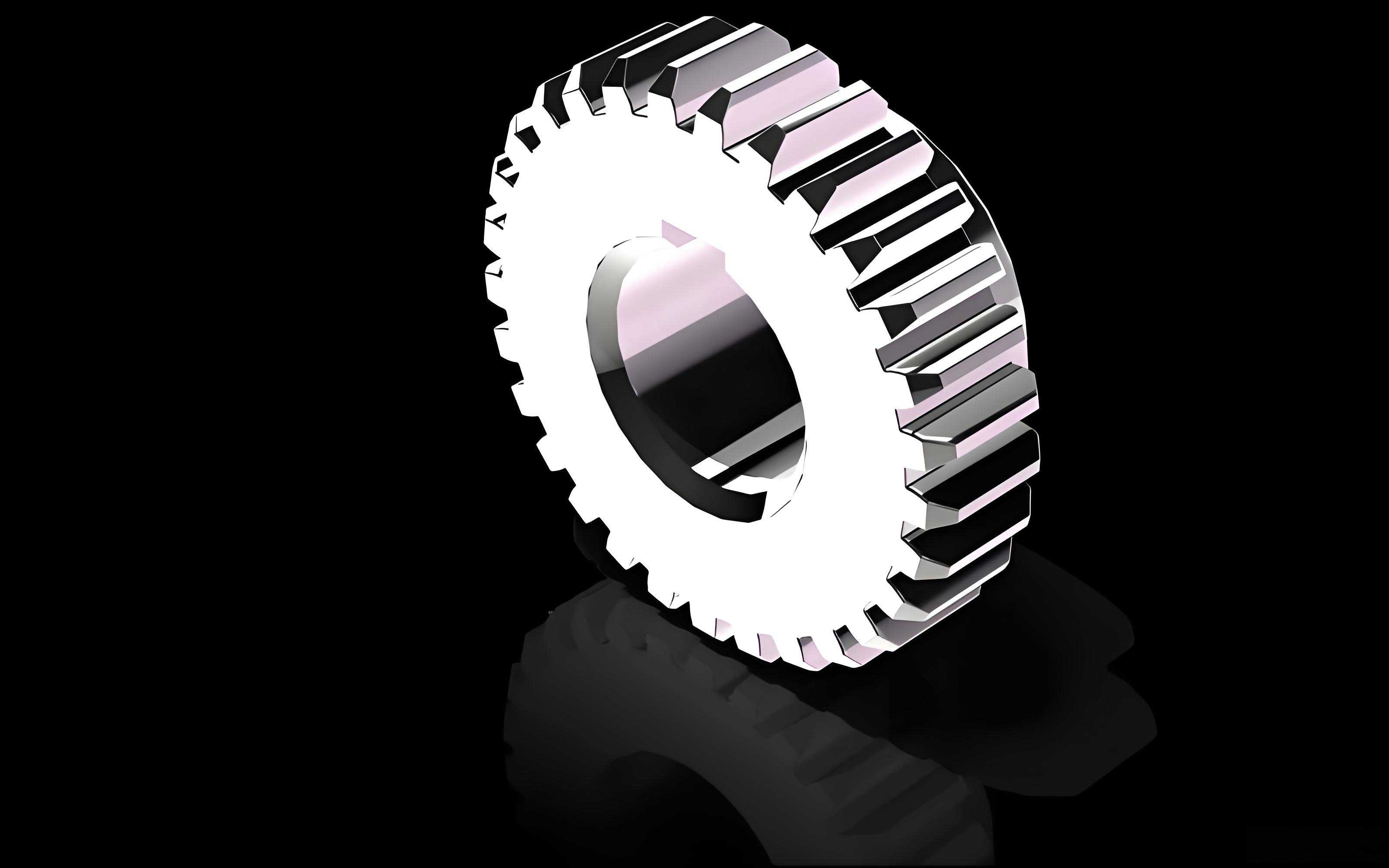
The specific component in focus is a duplex cylindrical spur gear intended for use in an electrical appliance. Both gear stages are standard involute spur gears with an identical module, requiring high dimensional accuracy and a flawless cosmetic appearance on the functional tooth flanks. The production volume is substantial, necessitating a mold design that prioritizes efficiency, automation, and longevity.
Material Selection and Processing Characteristics
The gear is molded from Polyoxymethylene (POM), a semi-crystalline engineering thermoplastic selected for its outstanding combination of properties crucial for gear performance. Key material characteristics influencing the mold design include:
- High Stiffness and Fatigue Resistance: Essential for maintaining tooth profile under load.
- Low and Predictable Shrinkage: Critical for achieving the precise geometry of a spur gear.
- Low Coefficient of Friction & Excellent Wear Resistance: Provides the desired self-lubricating behavior.
- Low Moisture Absorption: Ensures dimensional stability in varying environments, often eliminating the need for pre-drying.
However, POM is thermally sensitive, with a decomposition temperature around 240°C. Prolonged exposure even at 200°C can lead to degradation, releasing corrosive gases. This necessitates precise thermal control throughout the molding process. The general processing window involves a melt temperature slightly above its melting point, around 180-210°C, and a relatively high mold temperature of 80-120°C to promote crystallization and achieve optimal mechanical properties and dimensional stability. POM has a very low recommended flash gap (approx. 0.04 mm), demanding high clamping force and precise mold manufacturing. A comparison of key properties is shown in Table 1.
| Property | POM (Acetal) | 1018 Steel | AZ91D Magnesium |
|---|---|---|---|
| Density (g/cm³) | 1.41 | 7.85 | 1.81 |
| Tensile Strength (MPa) | 60-70 | 440 | 230 |
| Flexural Modulus (GPa) | 2.5-3.0 | 205 | 45 |
| Coefficient of Thermal Expansion (10⁻⁵ /K) | 8.1 – 11.0 | 1.2 | 2.6 |
| Poisson’s Ratio | 0.35 | 0.29 | 0.35 |
The component integrates a central metal insert made from 1045 steel to provide a robust, wear-resistant bore for shaft mounting. A critical design consideration is the difference in Coefficients of Thermal Expansion (CTE). The CTE of POM is approximately $8.1 \times 10^{-5} \, K^{-1}$, while for steel it is about $1.23 \times 10^{-5} \, K^{-1}$. Although not identical, this closer match (compared to, for example, aluminum) reduces the residual thermal stress at the plastic-metal interface after cooling, minimizing the risk of crack formation or debonding. The insert features knurling or grooves on its outer surface to enhance mechanical interlocking with the plastic.
Part Design Analysis and Gear Geometry
The duplex spur gear presents specific molding challenges. The primary goal is to replicate the precise involute tooth profile of both gear stages. The standard geometric parameters for a spur gear are defined below, where $m$ is the module, $z$ is the number of teeth, and $d$ is the diameter:
Pitch Diameter: $$d_p = m \cdot z$$
Addendum (Tip) Diameter: $$d_a = d_p + 2m = m(z + 2)$$
Dedendum (Root) Diameter: $$d_f = d_p – 2.5m = m(z – 2.5)$$
For this application, both gear stages share a module of $m = 0.5 \, \text{mm}$. The larger gear has $z_1 = 63$ teeth and the smaller gear has $z_2 = 50$ teeth. Applying the formulas:
- Large Spur Gear Pitch Diameter: $d_{p1} = 0.5 \times 63 = 31.50 \, \text{mm}$
- Large Spur Gear Tip Diameter: $d_{a1} = 0.5 \times (63 + 2) = 32.50 \, \text{mm}$
- Small Spur Gear Pitch Diameter: $d_{p2} = 0.5 \times 50 = 25.00 \, \text{mm}$
- Small Spur Gear Tip Diameter: $d_{a2} = 0.5 \times (50 + 2) = 26.00 \, \text{mm}$
These are the nominal part dimensions. The corresponding mold cavity dimensions must be enlarged to account for the material’s shrinkage. Assuming an average volumetric shrinkage, $S$, for POM of approximately 2.0%, the linear shrinkage factor, $k_s$, is approximately $S/3 \approx 0.67\%$. The cavity dimension, $D_{cavity}$, is calculated from the part dimension, $D_{part}$, as:
$$D_{cavity} = \frac{D_{part}}{1 – k_s}$$
For critical diameters like the tip diameter of the large spur gear:
$$D_{cavity, a1} \approx \frac{32.50}{1 – 0.0067} \approx 32.72 \, \text{mm}$$
This calculation is performed for all critical gear dimensions to generate the machining specifications for the cavity. The final calculated cavity dimensions, including manufacturing tolerances, are summarized in Table 2.
| Feature | Part Nominal Dimension | Calculated Cavity Dimension | Manufacturing Tolerance |
|---|---|---|---|
| Large Gear Tip Diameter | 32.50 | 32.72 | +0.03 / 0 |
| Large Gear Root Diameter | 30.25 | 30.45 | +0.03 / 0 |
| Large Gear Face Width | 3.50 | 3.52 | +0.02 / 0 |
| Small Gear Tip Diameter | 26.00 | 26.18 | +0.03 / 0 |
| Small Gear Root Diameter | 23.75 | 23.91 | +0.03 / 0 |
| Small Gear Face Width | 2.50 | 2.52 | +0.02 / 0 |
Mold Configuration and Core Design Philosophy
To meet high-volume production targets, a multi-cavity mold is essential. Given the part’s relatively small size and simple axial symmetry, a balanced four-cavity layout was selected. This layout, often arranged in an “H-pattern” or circular pattern around the sprue, ensures uniform filling and packing conditions across all cavities, critical for maintaining consistency in the precision spur gear dimensions. The mold is a three-plate design to facilitate automatic degating.
The most critical decision in mold design for this part is the selection of the primary parting line. For a duplex spur gear, the optimal parting line is located at the maximum outer diameter of the larger gear stage. This places the entire functional tooth profiles of both spur gears within a single mold half (typically the cavity side). This approach is superior to splitting the gear profile across two mold halves because it eliminates any potential mismatch or flash on the critical tooth flanks, which would severely impact meshing performance and noise. Any minor flash formed at the parting line will be on the non-functional face of the gear, where it can be easily tolerated or removed.
Given the complexity of machining a precise internal spur gear profile, the cavity is designed as a hardened, insert-type block. This “cavity insert” is machined as a separate component, typically from pre-hardened tool steel like P20 or H13, and then precision-fitted into a pocket machined in the cavity retainer plate. This method simplifies manufacturing, allows for selective hardening of the critical forming surfaces, and enables easy replacement in case of damage or wear. The insert is secured from the bottom with a support plate and screws.
The core side, which forms the internal bore and backs up the metal insert, employs a combination of components for functionality and serviceability. A primary core pin forms the main bore of the gear. Crucially, a separate insert locating pin is integrated into the core system. This pin, potentially made from beryllium copper for its superior thermal conductivity, protrudes through the core and precisely engages a pre-machined hole in the metal insert during mold closing. This positive location prevents any radial movement or rotation of the insert during the injection and packing phases, guaranteeing the concentricity of the insert bore relative to the molded spur gear teeth—a critical quality parameter. The use of a separate locating pin, rather than incorporating the feature into the main core, simplifies machining and maintenance. The core assembly is typically a “stack” consisting of the locating pin, the main core pin, and a push sleeve, all mounted on the ejector plate. This is a classic combination-type core structure, as referenced in the source.
Feed System and Gating Strategy
The feed system must deliver the polymer melt to the cavities while meeting strict cosmetic requirements. A cold runner, three-plate system is employed. The primary sprue transitions into a branched runner system leading to each cavity. Runners are trapezoidal or U-shaped in cross-section for a favorable surface-area-to-volume ratio, promoting cooling and material economy.
Gating is the most critical aspect. A pin-point gate, also known as a restrictor gate, is the optimal choice for this spur gear application. The gate is located centrally on the non-functional face of the smaller gear, adjacent to the metal insert. The advantages are numerous:
- Automatic Degating: The small gate diameter (typically 0.8 – 1.2 mm) allows it to break cleanly upon opening of the secondary parting plane, separating the part from the runner system automatically.
- Excellent Surface Finish: It leaves only a small, subtle mark on a non-critical surface, preserving the flawless appearance of the spur gear tooth flanks.
- Balanced Filling: A central gate promotes symmetric, radial flow into the cavity, which is ideal for a cylindrical part like a spur gear, minimizing weld lines and orientation-induced stresses.
- Good Control: The restricted orifice provides high shear, reducing melt viscosity for easier filling, and allows for quick sealing to control packing time.
The pressure drop, $\Delta P_{gate}$, across a pin-point gate can be approximated using the Hagen-Poiseuille equation for a short tube, modified for non-Newtonian flow:
$$\Delta P_{gate} \approx \frac{8 \mu Q L}{\pi R^4}$$
where $\mu$ is the melt viscosity, $Q$ is the volumetric flow rate, $L$ is the gate land length (very short, ~0.5 mm), and $R$ is the gate radius. This equation highlights why gate size is critical; a small change in radius $R$ has a fourth-power effect on pressure drop.
Temperature Control System Design
Effective mold temperature control is paramount for processing POM and achieving dimensionally stable spur gears. A high mold temperature (90-120°C) is required to ensure proper crystallization and to minimize molded-in stresses, which could lead to warpage or poor fatigue performance. Therefore, the system is designed as a heating circuit, using pressurized hot water or oil as the thermal medium.
Cooling channels are still necessary to extract heat from the mold after the initial high-temperature phase to achieve a practical cycle time. The system is a dual-purpose circuit. The channels are drilled in a serial or parallel layout in both the cavity insert and core plates, following standard design rules: channel diameter $D_c$ is often 8-12 mm, and the pitch distance from the cavity surface $P$ is typically 1.5 to 3 times $D_c$. For a small, thick-walled part like a spur gear, a circuit around the cavity perimeter is often sufficient.
The required heat load, $Q_{total}$, that must be managed per cycle consists of the heat to raise the polymer to the ejection temperature and the heat from the circulating medium:
$$Q_{total} = n \cdot m_{part} \cdot [C_p (T_{melt} – T_{eject}) + \Delta H_f]$$
where $n$ is the number of cavities (4), $m_{part}$ is the part mass, $C_p$ is the specific heat of POM, $T_{melt}$ is the melt temperature, $T_{eject}$ is the ejection temperature, and $\Delta H_f$ is the latent heat of fusion (for semicrystalline POM, this is significant). The cooling time $t_c$ can be estimated from the Fourier number for a cylinder (approximating the gear):
$$t_c \approx \frac{s^2}{\pi^2 \alpha} \ln\left[\frac{4}{\pi} \cdot \frac{T_{mold} – T_{melt}}{T_{eject} – T_{mold}}\right]$$
where $s$ is the maximum wall thickness (gear face width), $\alpha$ is the thermal diffusivity of POM, and $T_{mold}$ is the set mold temperature. Optimized process parameters are summarized in Table 3.
| Parameter | Value / Range | Unit | Rationale |
|---|---|---|---|
| Melt Temperature (Cylinder) | 185 – 200 | °C | Above melting point, below decomposition. |
| Mold Temperature | 90 – 100 | °C | Promotes crystallization, reduces stress. |
| Injection Pressure | 80 – 120 | MPa | High pressure for dense packing, overcoming gate restriction. |
| Injection Speed | Medium-High | – | Fast fill to prevent premature freezing at gate. |
| Packing Pressure & Time | 60% of Inj. Pressure, 3-5 sec | – | Compensates for shrinkage, avoids overpacking. |
| Cooling Time | 15 – 25 | sec | Based on wall thickness calculation. |
| Insert Pre-heat Temperature | 110 – 130 | °C | Reduces thermal shock, improves bond, minimizes stress. |
Ejection System and Mold Operation Sequence
The cylindrical shape of the duplex spur gear makes it susceptible to deformation if ejected unevenly. A sleeve-type ejector, or push sleeve, is the ideal solution. The sleeve surrounds the core pin and applies a perfectly uniform, annular ejection force to the back face of the larger gear or a supporting web. This prevents any bending or distortion of the relatively thin-walled gear sections. The push sleeve is mounted on the ejector plate and travels on guide pins. Return pins ensure the ejector system retracts before the mold closes for the next cycle.
The automated cycle of the three-plate mold is as follows:
- Mold Closing & Injection: The mold closes, with the insert locating pin engaging the metal insert. The cavity is injected with molten POM.
- Cooling & Plasticating: The part cools and solidifies under pressure while the next shot is prepared.
- Primary Opening (Runner Plate Break): The machine platen opens. Springs between the runner plate and cavity plate cause the first parting plane to open. The pin-point gates shear, and the runner system, held by the sprue puller, is pulled from the fixed half.
- Secondary Opening (Main Parting Line Break): After a predetermined travel, the runner plate is stopped by limit bolts. The mold continues to open at the main parting line, separating cavity and core. The molded duplex spur gear parts, now released from the cavities, remain on the core side.
- Ejection: The machine’s ejection system advances, driving the ejector plate forward. The push sleeves uniformly eject all four spur gear assemblies from the core pins.
- Ejector Retraction & Mold Close: The ejection system retracts, the runner system drops by gravity, and the mold closes to begin the next cycle.
This sequence enables fully automated, high-efficiency production.
Conclusion
The successful injection molding of a precision duplex plastic spur gear hinges on a holistic design approach that integrates material science, gear geometry, and advanced mold engineering. This design addresses the core challenges: achieving the micron-level accuracy required for the involute tooth profile of both spur gear stages, managing the integration of a dissimilar metal insert without inducing stress, and maintaining flawless surface quality. Key solutions implemented include a four-cavity balanced layout for productivity, a single-cavity-insert strategy with a parting line on the gear face to preserve tooth profile integrity, a positive insert locating pin for concentricity assurance, a pin-point gating system for automatic operation and cosmetic finish, a heated temperature control system for optimal POM processing, and a sleeve ejection mechanism to prevent part deformation. Through meticulous calculation of shrinkage, flow, and thermal dynamics, and the optimization of process parameters, this mold design achieves robust, automated production of high-quality duplex spur gears, demonstrating the sophisticated capabilities of modern plastic gear manufacturing.