
Purpose and context. When I examine product and technology decisions in heavy machinery, I see that transport weight, outer dimensions, lifting capacity, duty cycle, and manufacturing constraints constantly reshape structural forms. In tracked crane frames, for example, many changes have appeared because transport weight and envelope dimensions force designers to reconsider how material is distributed, how loads are transferred, and how stiffness and stability are maintained. Even so, the basic structural families of most frames have not changed radically. Therefore, I consider it necessary to identify the features that remain stable across those structural families, isolate the common load-bearing configuration, and then analyze that configuration with finite element methods. I follow the same logic for a forged gear blank. A forged gear blank is not merely a piece of metal that later becomes a gear; it is the first committed expression of a manufacturing strategy, a load path, a material flow pattern, and a thermal history. If I understand the forged gear blank correctly, I can open the design space for later gear cutting, heat treatment, and service performance. The same finite element reasoning that helps me understand frame structures helps me understand the deformation of a forged gear blank under a hydraulic press.
Gears are among the primary foundational components of mechanical equipment. Many mechanical transmissions are realized by mechanisms composed of gears, and their applications extend across lifting, shipping, rolling mills, mining, and many other engineering domains. In traditional processing, gear manufacturing proceeds through blank heat treatment, gear blank machining, tooth profile machining, tooth end machining, tooth surface heat treatment, datum correction, and tooth profile finishing. I treat each of these steps as a boundary condition on the forged gear blank, because the quality of the forged gear blank determines how much machining is required, how uniform the final properties become, and how reliably the gear performs. In recent years, precision forging has become a new process and a new technology with strong development prospects. Compared with traditional cutting methods, precision forging can raise material utilization of the forged gear blank above seventy percent, increase gear strength by more than twenty percent, and improve production efficiency by about forty percent. My focus is the forging stage of the forged gear blank, especially the numerical simulation of the billet forging process. By simulating the forged gear blank, I can improve material utilization while observing the internal streamline condition of the metal during billet forging, optimizing the forming process scheme for the forged gear blank, and improving the mechanical performance of the gear part.
From structural evolution to a forged gear blank. I begin with a broad design review because a forged gear blank is also a structural object. Its cross-section, volume distribution, symmetry, draft, fillet, and cavity contact condition determine whether metal flows smoothly or becomes trapped in a region of high shear. In the same way that a tracked crane frame must be evaluated for bending, torsion, and stability, a forged gear blank must be evaluated for effective strain, effective stress, temperature, contact pressure, and flow line continuity. I do not want to treat the forged gear blank as a rigid shape that simply fills a die. I want to treat the forged gear blank as a deforming continuum whose final geometry and internal state are produced by the interaction among the billet, the dies, friction, temperature, and press motion.
The typical gear blank in my study is a disk-shaped part. I use a material equivalent to 45 steel, and for the billet I select 45# bar stock. The shape of the billet is relatively simple, so I can form it in a single forging operation. Based on preliminary calculation, I can choose two specifications for the billet: one with diameter and length of 85 mm by 130 mm, and another with diameter and length of 100 mm by 94 mm. The final choice depends on the numerical simulation of the forging process. I compare the two candidate billets because the die opening has a diameter of 85 mm. This geometric relationship is decisive for the forged gear blank. If the billet diameter equals the die opening, the initial contact occurs mainly at the end faces. If the billet diameter is larger than the die opening, the initial contact occurs first at the oversized shoulder, and the deformation history changes. I want to know which billet produces a more uniform forged gear blank, a smoother flow line pattern, and a more favorable temperature distribution.
Traditional route versus precision forging for a forged gear blank. The traditional route for producing a gear is multi-stage and subtractive. It consumes material, interrupts the flow lines, and often requires repeated thermal and mechanical operations. Precision forging is attractive because it produces a forged gear blank that is close to the final shape, preserves continuous flow lines, and reduces the need for later machining. I summarize the comparison in the table below.
| Comparison item | Traditional cutting route for a forged gear blank | Precision forging route for a forged gear blank |
|---|---|---|
| Primary forming mechanism | Material removal from a blank | Plastic flow and cavity filling of the forged gear blank |
| Material utilization | Lower, often with significant chip loss | Can exceed 70 percent for the forged gear blank |
| Flow line continuity | Interrupted by cutting | Continuous and tailored through the forged gear blank |
| Gear strength | Baseline | Can increase by more than 20 percent |
| Production efficiency | Baseline | Can increase by about 40 percent |
| Typical process sequence | Blank heat treatment, gear blank machining, tooth profile machining, tooth end machining, tooth surface heat treatment, datum correction, tooth profile finishing | Billet preparation, heating, die forging of the forged gear blank, controlled cooling, finishing, heat treatment |
| Main design concern | Datum stability and machining allowance | Metal flow, cavity fill, temperature field, and forging load of the forged gear blank |
I express the improvement in material utilization for the forged gear blank as a ratio. If the initial billet volume is \(V_0\) and the final forged part volume is \(V_f\), then the material utilization is
$$ \eta_m = \frac{V_f}{V_0} \times 100\% $$
For precision forging of the forged gear blank, I seek
$$ \eta_m \ge 70\% $$
I also express the strength improvement as
$$ \Delta \sigma = \frac{\sigma_p – \sigma_c}{\sigma_c} \times 100\% \ge 20\% $$
where \(\sigma_p\) is the strength obtained through precision forging of the forged gear blank and \(\sigma_c\) is the strength obtained through the traditional cutting route. The productivity improvement can be written as
$$ \Delta P = \frac{P_p – P_c}{P_c} \times 100\% \approx 40\% $$
These relations are simple, but they remind me that the forged gear blank is not only a geometric intermediate. It is the carrier of material efficiency, mechanical property improvement, and production speed.
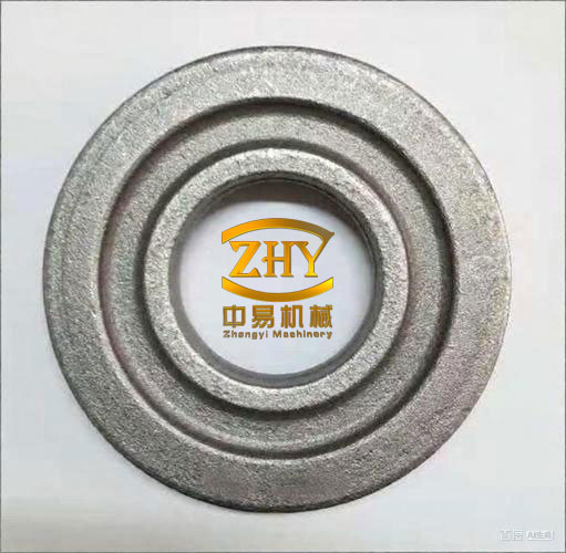
Why I simulate the forged gear blank. Numerical simulation allows me to observe the internal state of the forged gear blank without cutting it open. I can follow metal flow, temperature evolution, effective strain, contact pressure, and cavity filling step by step. I can also compare candidate billets before committing to tooling. For a forged gear blank, the most important questions are whether the metal reaches the tooth root region completely, whether the flow lines remain smooth, whether the temperature field remains symmetric, and whether the press load stays within the available capacity. Simulation gives me a controlled view of these questions. I use MARC.SuperForm because it is a volume-forming finite element simulation software with strong capabilities in graphics processing, user interface, data structure, and pre- and post-processing. Its workflow can be divided into five modules, and I summarize them below.
| Module | Function in my forged gear blank study | Key inputs or outputs |
|---|---|---|
| Billet and die geometry drawing | I draw the billet, the fixed die, and the moving die for the forged gear blank with accurate dimensions. | Billet diameter, billet length, die cavity, die opening, fillets, draft, and symmetry condition. |
| Material selection or material property definition | I define the deformation characteristics of the forged gear blank material. | Flow stress curves, temperature-dependent properties, strain-rate sensitivity, and thermal properties. |
| Deformation parameter input | I specify the initial conditions and machine parameters for the forged gear blank. | Initial temperature, friction coefficient, moving die position, velocity, press stage, and termination condition. |
| Finite element analysis | I solve the plastic forming problem for the forged gear blank. | Nodal velocity, strain, stress, temperature, contact state, and reaction force. |
| Visualization of simulation results | I display the calculated results as color contours and line layers for the forged gear blank. | Temperature contours, effective strain contours, flow lines, contact pressure, and fill state. |
The first three modules can be run in sequence or operated separately, which allows me to modify simulation conditions as needed. This flexibility is important because the forged gear blank geometry, material model, and process parameters are coupled. A small change in billet diameter changes the initial contact area, which changes friction, which changes temperature, which changes flow stress, which changes cavity filling. I therefore treat the simulation of the forged gear blank as an iterative design loop rather than a single calculation.
Model construction for the forged gear blank. I construct the model according to the actual sample. Because the gear part is axisymmetric, I set the symmetry axis as the X-axis and choose a mechanical axisymmetric model. This reduces the computational effort while preserving the essential behavior of the forged gear blank. I divide the domain into rectangular small elements. For the material, I select C45 from the material library. The initial state uses a temperature of 1250 degrees Celsius, which I treat as the initial forging temperature. I input a friction coefficient of 0.2. The moving die starts at a position of 200, 0 and terminates at 31.5, 0. For mesh regeneration, I choose an overlay quad strategy, set the maximum element edge length to 0.3, and specify the remesh body as the workpiece. For the deformation force, I choose the hydraulic press stage. The termination of the deformation process is defined by node-in-contact reaching one hundred percent on the workpiece. I summarize these settings in the table below.
| Parameter or setting | Value used for the forged gear blank | Reason or effect |
|---|---|---|
| Symmetry axis | X-axis | Exploits axisymmetry of the forged gear blank. |
| Model type | Mechanical axisymmetric | Reduces simulation size while retaining radial and axial deformation. |
| Mesh type | Rectangular small elements | Provides a stable initial discretization for the forged gear blank. |
| Material | C45, equivalent to 45 steel | Matches the selected 45# bar stock for the forged gear blank. |
| Initial temperature | 1250 degrees Celsius | Represents the initial forging temperature. |
| Friction coefficient | 0.2 | Controls interface friction between the forged gear blank and the dies. |
| Moving die initial position | 200, 0 | Defines the starting position before forging. |
| Moving die final position | 31.5, 0 | Defines the termination position of the forged gear blank. |
| Remesh method | Overlay quad | Maintains element quality as the forged gear blank deforms. |
| Maximum element edge length | 0.3 | Controls resolution and accuracy during remeshing. |
| Remesh body | Workpiece | Restricts remeshing to the forged gear blank. |
| Deformation force type | Hydraulic press stage | Represents the press characteristics. |
| Termination | Node in contact 100 percent on workpiece | Stops the simulation when contact and fill criteria are met. |
The finite element formulation for the forged gear blank can be understood through the virtual work principle. For a deforming body under quasi-static conditions, I write
$$ \int_V \sigma : \delta \varepsilon \, dV = \int_{S_f} f \cdot \delta u \, dS + \int_V b \cdot \delta u \, dV $$
where \(\sigma\) is the stress tensor, \(\delta \varepsilon\) is the virtual strain tensor, \(f\) is the surface traction, \(b\) is the body force, and \(\delta u\) is the virtual displacement. For the forged gear blank, the dominant surface traction comes from the dies, while body forces are small compared with forging loads. I also use the incompressibility condition appropriate to large plastic deformation:
$$ \nabla \cdot v = 0 $$
where \(v\) is the velocity field of the forged gear blank. The effective strain is evaluated as
$$ \bar{\varepsilon} = \int_0^t \sqrt{\frac{2}{3} \dot{\varepsilon}_{ij} \dot{\varepsilon}_{ij}} \, dt $$
and the effective stress is
$$ \bar{\sigma} = \sqrt{\frac{3}{2} s_{ij} s_{ij}} $$
where \(s_{ij}\) is the deviatoric stress tensor. The flow stress of the forged gear blank can be represented in a general form as
$$ \sigma_f = K \bar{\varepsilon}^{n} \dot{\bar{\varepsilon}}^{m} \exp\left(\frac{Q}{RT}\right) $$
where \(K\) is the strength coefficient, \(n\) is the strain-hardening exponent, \(m\) is the strain-rate sensitivity, \(Q\) is the activation energy, \(R\) is the gas constant, and \(T\) is the absolute temperature. For the forged gear blank, temperature enters both the flow stress and the heat transfer problem. I write the heat transfer equation as
$$ \rho c_p \left(\frac{\partial T}{\partial t} + v \cdot \nabla T\right) = \nabla \cdot (k \nabla T) + \dot{q}_{pl} $$
where \(\rho\) is density, \(c_p\) is specific heat, \(k\) is thermal conductivity, and \(\dot{q}_{pl}\) is the heat generation rate from plastic work. This equation is important because the temperature field of the forged gear blank influences flow stress, die contact, friction, and microstructure.
The friction condition at the die interface can be written in a simplified form as
$$ \tau_f = \mu p $$
where \(\tau_f\) is the friction shear stress, \(\mu\) is the friction coefficient, and \(p\) is the contact pressure. I set \(\mu = 0.2\) for the forged gear blank. The contact condition itself can be expressed through the normal gap and contact pressure:
$$ g_n \ge 0, \quad p_n \ge 0, \quad p_n g_n = 0 $$
These relations mean that the forged gear blank may separate from the die, but it may not penetrate the die. I also monitor the remeshing criterion
$$ h_{\max} \le 0.3 $$
to keep the element size within the prescribed limit. This is a numerical condition, but it has physical consequences because poor mesh quality can distort the predicted flow lines and temperature gradients in the forged gear blank.
Billet volume and material selection for the forged gear blank. I first estimate the volume of each candidate billet. For the first scheme, the billet has diameter 85 mm and length 130 mm. The radius is 42.5 mm. Therefore,
$$ V_1 = \pi \left(\frac{85}{2}\right)^2 \times 130 $$
$$ V_1 = \pi (42.5)^2 \times 130 $$
$$ V_1 = \pi \times 1806.25 \times 130 $$
$$ V_1 = 234812.5\pi \approx 7.377 \times 10^5 \, \text{mm}^3 $$
For the second scheme, the billet has diameter 100 mm and length 94 mm. The radius is 50 mm. Therefore,
$$ V_2 = \pi \left(\frac{100}{2}\right)^2 \times 94 $$
$$ V_2 = \pi (50)^2 \times 94 $$
$$ V_2 = \pi \times 2500 \times 94 $$
$$ V_2 = 235000\pi \approx 7.383 \times 10^5 \, \text{mm}^3 $$
The two volumes are almost identical. The difference is
$$ \Delta V = V_2 – V_1 \approx 6.87 \times 10^2 \, \text{mm}^3 $$
$$ \frac{\Delta V}{V_1} \approx 0.093\% $$
This small volume difference means that the comparison is not primarily about material quantity. It is about initial geometry. The forged gear blank produced from the first billet starts with a diameter equal to the die opening, while the forged gear blank produced from the second billet starts with a diameter larger than the die opening. That difference changes the contact sequence, the friction path, the deformation zone, and the final streamline pattern. I summarize the two schemes below.
| Scheme | Billet specification for the forged gear blank | Billet volume | Relation to die opening | Number of deformation steps |
|---|---|---|---|---|
| Scheme one | 85 mm diameter by 130 mm length | Approximately \(7.377 \times 10^5 \, \text{mm}^3\) | Diameter equals the die opening | 92 |
| Scheme two | 100 mm diameter by 94 mm length | Approximately \(7.383 \times 10^5 \, \text{mm}^3\) | Diameter exceeds the die opening | 107 |
Simulation of the forged gear blank in scheme one. In scheme one, I use the 85 mm by 130 mm bar stock. The deformation runs for 92 steps. At the initial position, the left side is the fixed die and the right side is the moving die. The moving die travels in the negative X direction, and the X-axis is the symmetry axis of the forged gear blank. When the two ends of the billet come into complete contact with the moving die and the fixed die, the metal is forced to move toward the empty space in the die cavity. The two contact points and the central region of the billet experience the most severe deformation. As the forged gear blank continues to deform, friction is generated between the metal and the die cavity, and the temperature of the metal near the cavity surface increases. The deformation continues, the internal temperature rises, and the deformation zone expands. When the metal that has flowed into the empty cavity reaches the top of the die, the metal begins to fill the tooth root region of the forged gear blank. At the end of the process, the temperature distribution inside the forged gear blank is approximately left-right symmetric, and the deformation is relatively uniform. I regard this as a favorable result because a symmetric temperature field and a uniform deformation field reduce the risk of distortion, property gradients, and incomplete filling.
I can describe the local filling behavior of the forged gear blank with a simple volume balance. If \(V_{\text{cavity}}\) is the available cavity volume and \(V_{\text{flow}}\) is the volume of metal that has entered the cavity, then the fill ratio is
$$ R_f = \frac{V_{\text{flow}}}{V_{\text{cavity}}} $$
At the end of a successful forging process for the forged gear blank, I require
$$ R_f \approx 1 $$
In scheme one, the movement of metal into the cavity is progressive and reaches the tooth root region in a stable manner. The flow lines remain continuous and relatively smooth. The effective strain distribution is not perfectly uniform, because forging always produces gradients, but the gradients are acceptable and the forged gear blank fills completely.
Simulation of the forged gear blank in scheme two. In scheme two, I use the 100 mm by 94 mm bar stock. The deformation runs for 107 steps. The key difference from scheme one is that the billet diameter is increased from 85 mm to 100 mm, which exceeds the lower die diameter range of 85 mm. At the beginning, the part of the billet that exceeds the 85 mm cavity dimension contacts the die first. The metal begins to deform, and the two contact points experience severe deformation. Unlike scheme one, the center of the billet does not deform at the beginning. As the process continues, only the metal outside the 85 mm dimension deforms. Under the pressure, this metal moves toward the upper empty cavity of the die. The contact regions between the metal and the moving and fixed dies have not yet experienced the same friction history as in scheme one. The billet continues to deform under pressure. The central region of the billet begins to deform, the temperature rises, and excess metal is squeezed into the upper cavity of the die. The metal flowing into the cavity eventually contacts the top of the die, and the metal begins to fill the tooth root region of the forged gear blank. At the end of the deformation process, the temperature inside the billet is not completely symmetric. In particular, the region of the metal in contact with the moving die has the highest temperature, and the temperature gradient is relatively large. I regard this as a less favorable result because a large temperature gradient can produce uneven flow stress, uneven recrystallization, and a less uniform forged gear blank.
The contact sequence in scheme two can be summarized by a contact fraction. If \(A_c\) is the current contact area and \(A_t\) is the total die interface area, then
$$ C_f = \frac{A_c}{A_t} $$
For the forged gear blank, a contact fraction that rises too quickly at the shoulder can create a localized deformation band. A contact fraction that rises too slowly at the center can delay the initiation of central flow. I want the contact fraction to increase in a balanced way, so that the forged gear blank fills the cavity without excessive local heating or shear localization. Scheme two shows a less balanced contact evolution than scheme one.
Comparative evaluation of the forged gear blank. I compare the two schemes across several criteria: initial contact, central deformation, flow line continuity, temperature symmetry, cavity filling, tooth root filling, number of steps, and final suitability. I present the comparison in the table below.
| Evaluation criterion | Scheme one: 85 mm by 130 mm forged gear blank | Scheme two: 100 mm by 94 mm forged gear blank |
|---|---|---|
| Initial contact condition | End faces contact the dies, and central deformation begins early. | Oversized shoulder contacts first, and central deformation is delayed. |
| Deformation zone evolution | Deformation expands from the ends and center in a balanced manner. | Deformation is initially concentrated outside the die opening. |
| Flow line continuity | Smooth and relatively symmetric flow lines. | Less symmetric flow lines with stronger local shearing. |
| Temperature symmetry | Temperature field is approximately left-right symmetric. | Temperature field is not fully symmetric and has a large gradient near the moving die. |
| Cavity filling | Metal enters the empty cavity progressively and fills the forged gear blank well. | Metal movement is delayed and more dependent on shoulder deformation. |
| Tooth root filling | Tooth root region is filled after stable cavity flow. | Tooth root filling occurs later and with less uniform temperature support. |
| Number of deformation steps | 92 | 107 |
| Overall assessment | More reasonable deformation and better uniformity. | Less favorable deformation and less uniform final state. |
| Selected billet | Yes | No |
After comparing scheme one and scheme two, I conclude that scheme one is more reasonable. The deformation of the forged gear blank is more uniform, the metal flow lines are smoother, and the temperature field is more symmetric. Therefore, I select the 85 mm by 130 mm bar stock as the billet for the forged gear blank. This conclusion is not based only on a visual impression. It follows from the coupled behavior of contact, friction, plastic flow, and heat generation. The forged gear blank with the smaller initial diameter avoids the early shoulder contact that dominates scheme two. It allows the deformation to begin at the ends and center, which promotes a more balanced flow field. It also produces a temperature distribution that is closer to symmetric, which is beneficial for subsequent processing and final gear performance.
Temperature field and its meaning for the forged gear blank. The temperature field of the forged gear blank is not a secondary result. It is a central process variable. Plastic deformation generates heat, friction generates heat, and heat conduction redistributes that energy. I use the heat equation
$$ \rho c_p \left(\frac{\partial T}{\partial t} + v \cdot \nabla T\right) = \nabla \cdot (k \nabla T) + \dot{q}_{pl} $$
to describe this behavior. The plastic work term \(\dot{q}_{pl}\) can be approximated as
$$ \dot{q}_{pl} = \beta \bar{\sigma} \dot{\bar{\varepsilon}} $$
where \(\beta\) is the fraction of plastic work converted into heat. For the forged gear blank, a high temperature near the moving die contact region indicates that friction and plastic dissipation are concentrated there. A large temperature gradient is undesirable because it creates a local decrease in flow stress and can cause uneven deformation. In scheme two, the temperature is not completely symmetric, and the region in contact with the moving die reaches the highest temperature with a large gradient. In scheme one, the temperature is approximately left-right symmetric. This means that the forged gear blank in scheme one is more likely to develop uniform grain structure and more consistent mechanical properties.
I can also define a temperature non-uniformity index for the forged gear blank as
$$ U_T = \frac{T_{\max} – T_{\min}}{\bar{T}} $$
where \(T_{\max}\) is the maximum temperature, \(T_{\min}\) is the minimum temperature, and \(\bar{T}\) is the average temperature. A smaller \(U_T\) indicates a more uniform temperature field. I do not need a perfect isothermal field, because forging is inherently non-isothermal, but I want \(U_T\) to remain within a range that avoids hot spots, cold shuts, and incomplete filling. Scheme one gives a more favorable \(U_T\) than scheme two.
Stress, strain, and flow line condition of the forged gear blank. The effective strain and effective stress of the forged gear blank describe the intensity of plastic deformation. I evaluate them through
$$ \bar{\varepsilon} = \int_0^t \sqrt{\frac{2}{3} \dot{\varepsilon}_{ij} \dot{\varepsilon}_{ij}} \, dt $$
$$ \bar{\sigma} = \sqrt{\frac{3}{2} s_{ij} s_{ij}} $$
The flow lines of the forged gear blank follow the material particle paths. If the flow lines are smooth, they indicate that the deformation is well distributed. If the flow lines are folded, broken, or sharply diverted, they indicate local shear bands, dead zones, or unfavorable cavity geometry. In scheme one, the flow lines are smoother and more symmetric. In scheme two, the initial oversized shoulder creates a local deformation concentration, and the flow lines are less symmetric. I prefer the smoother flow line pattern because it is beneficial for the mechanical performance of the final gear. A forged gear blank with continuous flow lines can provide better fatigue resistance and better load transmission than a forged gear blank with abrupt internal discontinuities.
The velocity field of the forged gear blank can be written as
$$ v = v_r e_r + v_z e_z $$
in an axisymmetric coordinate system. The strain-rate components are
$$ \dot{\varepsilon}_{rr} = \frac{\partial v_r}{\partial r} $$
$$ \dot{\varepsilon}_{zz} = \frac{\partial v_z}{\partial z} $$
$$ \dot{\varepsilon}_{\theta\theta} = \frac{v_r}{r} $$
$$ \dot{\varepsilon}_{rz} = \frac{1}{2}\left(\frac{\partial v_r}{\partial z} + \frac{\partial v_z}{\partial r}\right) $$
These components help me identify where the forged gear blank is deforming most severely. In scheme one, the strain-rate distribution is more balanced between the axial and radial directions. In scheme two, the radial flow associated with the oversized shoulder is more dominant at the beginning, which delays the axial filling of the forged gear blank.
Press load and energy for the forged gear blank. The forging load is an important practical constraint. The hydraulic press stage in the simulation provides the deformation force. I estimate the load evolution by integrating the contact pressure over the die interface:
$$ F = \int_{A_c} p_n \, dA $$
where \(F\) is the forging force, \(A_c\) is the contact area, and \(p_n\) is the normal contact pressure. The plastic work is
$$ W_p = \int_V \int_0^t \bar{\sigma} \dot{\bar{\varepsilon}} \, dt \, dV $$
and the friction work is
$$ W_f = \int_{A_c} \int_0^t \tau_f v_s \, dt \, dA $$
where \(v_s\) is the sliding velocity between the forged gear blank and the die. These quantities help me evaluate whether the selected process is efficient. A process that requires excessive load or generates excessive friction work may be less practical, even if the final geometry is acceptable. In my comparison, scheme one reaches a stable filling condition with fewer deformation steps than scheme two. This suggests that the forged gear blank in scheme one can be produced with a more direct load path and less redundant shearing.
Remeshing and numerical reliability. Large deformation in the forged gear blank causes element distortion. I use remeshing to maintain accuracy. The criterion is
$$ h_{\max} \le 0.3 $$
and the remesh body is the workpiece. The overlay quad method helps preserve the solution field while improving element quality. I pay attention to remeshing because it can influence the predicted flow lines and temperature gradients. If remeshing is too coarse, the forged gear blank may appear to fill correctly while local defects are missed. If remeshing is too fine, the simulation cost increases. I choose the maximum element edge length as 0.3 to balance accuracy and efficiency. I also use node-in-contact reaching one hundred percent on the workpiece as the termination condition. This ensures that the forged gear blank has complete contact with the die before I stop the simulation. The termination condition is
$$ C_{\text{node}} = 100\% $$
on the workpiece. This is a practical criterion for a forged gear blank because incomplete contact can indicate incomplete filling.
Process optimization for the forged gear blank. The simulation does not end with a comparison. It leads to process optimization. I can adjust billet dimensions, die fillet radii, friction conditions, initial temperature, and press velocity to improve the forged gear blank. I can also use the simulation to reduce flash, avoid laps, and control grain flow. The main optimization variables for the forged gear blank are listed below.
| Optimization variable | Effect on the forged gear blank | Desired direction |
|---|---|---|
| Billet diameter | Controls initial contact and shoulder deformation. | Match the die opening when possible to avoid early shoulder contact. |
| Billet length | Controls volume distribution and axial flow distance. | Provide enough volume without excessive flash. |
| Initial temperature | Controls flow stress and heat generation. | Maintain a temperature range that promotes flow without overheating. |
| Friction coefficient | Controls surface flow, contact heating, and load. | Use appropriate lubrication to avoid excessive friction. |
| Die fillet radius | Controls local shear and cavity filling. | Use sufficiently large radii to avoid flow lines that are too sharp. |
| Press velocity | Controls strain rate and temperature rise. | Select a velocity that fills the cavity without excessive local heating. |
| Remesh size | Controls numerical resolution of the forged gear blank. | Keep element size small enough to resolve flow lines and temperature gradients. |
I find that the forged gear blank is sensitive to initial diameter. This is an important design insight. A small change in billet diameter can shift the initial contact from the end faces to the shoulder. That shift changes the entire deformation history. In scheme one, the 85 mm diameter matches the die opening. The forged gear blank starts with end-face contact and central deformation. In scheme two, the 100 mm diameter exceeds the die opening. The forged gear blank starts with shoulder contact and delayed central deformation. The first path is more favorable. I therefore recommend the 85 mm by 130 mm billet for the forged gear blank.
Material utilization and property improvement for the forged gear blank. Precision forging of the forged gear blank offers strong advantages. I can represent the material saving as
$$ S_m = V_0 – V_f $$
where \(S_m\) is the volume of material saved relative to the initial billet. The utilization ratio is
$$ \eta_m = \frac{V_f}{V_0} \times 100\% $$
For the forged gear blank, I aim for \(\eta_m \ge 70\%\). This is not only an economic target. A higher utilization ratio often means that the flow lines are better aligned with the final part and that less material is cut away. The mechanical property improvement can be expressed as
$$ \Delta \sigma = \frac{\sigma_p – \sigma_c}{\sigma_c} \times 100\% \ge 20\% $$
and the productivity improvement as
$$ \Delta P = \frac{P_p – P_c}{P_c} \times 100\% \approx 40\% $$
These benefits depend on a well-designed forging process. If the forged gear blank is not filled properly, or if the temperature field is highly non-uniform, the potential property improvement may not be realized. This is why I insist on numerical simulation before tooling. The forged gear blank must be evaluated as a coupled thermomechanical system.
Comparison with the design logic of tracked crane frames. I return briefly to the broader product and technology context because it clarifies my method. In tracked crane frames, transport weight and outer dimensions have forced changes in structural form, but the basic structural types have not changed dramatically. The same is true for the forged gear blank. The basic forging process has not changed: a billet is heated, placed in a die, compressed, and shaped. What changes is the detail of the forged gear blank: billet dimensions, contact sequence, flow line pattern, temperature distribution, and final properties. By identifying the stable features and analyzing the common load-bearing or material-flow configuration, I can open the design space. For the forged gear blank, the stable feature is the axisymmetric disk-like geometry and the single forging operation. The variable feature is the initial billet aspect ratio. By simulating that variable, I can make a better decision.
I also see a parallel in the need for finite element analysis. A tracked crane frame must be analyzed for stress, stiffness, and stability. A forged gear blank must be analyzed for stress, strain, temperature, and fill. In both cases, finite element analysis is not an ornament. It is a decision tool. It helps me see what cannot be seen directly, and it helps me compare alternatives before committing resources. The forged gear blank is a perfect example because the internal flow lines and temperature field are invisible during the forging operation. Simulation makes them visible.
Detailed interpretation of the two schemes. I expand the comparison with additional observations. In scheme one, the initial billet diameter equals the die opening. This means that the radial constraint at the die entrance is immediate and uniform. The metal at the end faces contacts the dies first, and the central region begins to deform early. The deformation zone spreads inward and outward in a balanced way. The friction between the metal and the die cavity increases the temperature near the contact surfaces, but the temperature remains approximately symmetric. When the metal reaches the top of the die, it begins to fill the tooth root region. The final forged gear blank has a relatively uniform temperature and deformation state. In scheme two, the initial billet diameter is larger than the die opening. The shoulder contacts the die first, and the center remains relatively undeformed at the beginning. The metal outside the die opening deforms severely, while the center lags. The flow into the upper cavity is delayed. When the center finally deforms, the temperature distribution is already asymmetric. The region in contact with the moving die becomes hotter, and the temperature gradient becomes large. The final forged gear blank is less uniform. These differences are subtle in geometry but significant in material state.
I can quantify the deformation uniformity with a strain non-uniformity index:
$$ U_{\varepsilon} = \frac{\bar{\varepsilon}_{\max} – \bar{\varepsilon}_{\min}}{\bar{\varepsilon}_{\text{avg}}} $$
A smaller \(U_{\varepsilon}\) indicates a more uniform forged gear blank. Based on the flow behavior, scheme one produces a smaller \(U_{\varepsilon}\) than scheme two. This supports my selection. I can also define a flow line quality index based on curvature and continuity, but that is more difficult to express analytically. I therefore rely on the contour plots and the streamline visualization. The forged gear blank in scheme one shows smoother line layers and fewer abrupt changes. The forged gear blank in scheme two shows stronger local curvature and a less symmetric pattern.
Practical implications for tooling and production. The selection of the 85 mm by 130 mm billet has practical implications. It reduces the tendency for shoulder contact, which in turn reduces the risk of local overheating near the moving die. It promotes central deformation, which helps fill the tooth root region of the forged gear blank. It produces a more symmetric temperature field, which simplifies subsequent heat treatment. It also requires fewer deformation steps in the simulation, which suggests a more direct forming path. I do not claim that fewer steps always mean lower cost in production, but in this case the shorter path is consistent with more uniform filling. I therefore recommend the 85 mm by 130 mm billet for the forged gear blank. I also recommend maintaining the friction coefficient near 0.2, controlling the initial temperature at 1250 degrees Celsius, and using the hydraulic press stage with the node-in-contact termination criterion. These settings produce a stable simulation of the forged gear blank and a reliable comparison between schemes.
Quality control and verification for the forged gear blank. After simulation, I would verify the forged gear blank through physical trials. The verification plan includes measuring the final dimensions, checking the fill of the tooth root region, inspecting the flow lines, and measuring hardness and microstructure at selected locations. I would compare the measured temperature history, if available, with the simulated temperature field. I would also compare the press load curve with the simulated load. If the physical forged gear blank shows incomplete filling or asymmetric flow, I would adjust the billet diameter, die fillet, friction condition, or initial temperature. The simulation is not a substitute for physical validation, but it is a powerful guide. It reduces the number of trials and makes each trial more informative. For the forged gear blank, this is especially valuable because trial forging is expensive and time-consuming.
I can express the verification condition for dimensional conformity as
$$ \delta_d = \frac{d_{\text{measured}} – d_{\text{target}}}{d_{\text{target}}} \times 100\% $$
and require
$$ |\delta_d| \le \delta_{\text{allow}} $$
where \(\delta_{\text{allow}}\) is the allowable dimensional deviation for the forged gear blank. I can also define a fill defect area \(A_{\text{defect}}\) and require
$$ A_{\text{defect}} \le A_{\text{allow}} $$
These criteria help me judge whether the forged gear blank is acceptable. In the simulation, scheme one shows a better fill condition and a more uniform temperature field, so I expect it to meet these criteria more easily than scheme two.
Why the forged gear blank benefits from axisymmetric modeling. The gear part is axisymmetric, so I use a mechanical axisymmetric model. This choice reduces the computational domain and allows a finer mesh for the forged gear blank. The X-axis is the symmetry axis. The radial coordinate and axial coordinate are sufficient to describe the deformation. The circumferential strain is not zero, but it is determined by the radial displacement through the axisymmetric condition. This is an efficient approach for the forged gear blank. It allows me to simulate the entire forging process with good resolution and acceptable computational time. The rectangular small elements provide a stable initial mesh. The overlay quad remeshing strategy maintains element quality as the forged gear blank deforms. The maximum element edge length of 0.3 ensures that the flow lines and temperature gradients are resolved. I consider this modeling strategy appropriate for the forged gear blank because it captures the essential physics without unnecessary three-dimensional complexity.
Heat generation and friction in the forged gear blank. Friction is a major source of heat at the die interface. I use
$$ \tau_f = \mu p $$
with \(\mu = 0.2\). The friction work is converted into heat, and the heat flows into both the die and the forged gear blank. In scheme one, the contact conditions are more balanced, so the friction heating is distributed more evenly. In scheme two, the oversized shoulder contacts the die first, so the friction heating is concentrated at the shoulder. This contributes to the large temperature gradient near the moving die. The forged gear blank in scheme two therefore has a less favorable thermal state. I prefer scheme one because it reduces the risk of local hot spots and promotes a more uniform microstructure.
Deformation steps and process stability. Scheme one requires 92 deformation steps in the simulation, while scheme two requires 107. The number of steps is not a direct production cost, but it indicates how the deformation evolves. A process that requires more steps to reach complete fill may involve more complex contact changes, more remeshing, and more opportunities for numerical error. In scheme two, the delayed central deformation and the shoulder-dominated flow create a more complex deformation history. In scheme one, the deformation is more direct. I therefore view the step count as supporting evidence, not as the primary criterion. The primary criteria are flow line continuity, temperature symmetry, fill quality, and deformation uniformity. Scheme one is superior in all these respects.
Summary of my numerical simulation for the forged gear blank. I set up an axisymmetric finite element model for the forged gear blank. I used C45 material, an initial temperature of 1250 degrees Celsius, a friction coefficient of 0.2, a moving die stroke from 200, 0 to 31.5, 0, overlay quad remeshing with a maximum element edge length of 0.3, a hydraulic press stage, and a node-in-contact termination condition of 100 percent on the workpiece. I compared two billets: 85 mm by 130 mm and 100 mm by 94 mm. The first produced 92 deformation steps. The second produced 107 deformation steps. The first produced a more uniform deformation, smoother flow lines, and a more symmetric temperature field. The second produced delayed central deformation, less symmetric flow lines, and a large temperature gradient near the moving die. I therefore selected the 85 mm by 130 mm billet for the forged gear blank. This choice supports better material utilization, better mechanical performance, and more reliable subsequent processing.
Key equations for the forged gear blank. I collect the most important relations in one place for clarity.
$$ \eta_m = \frac{V_f}{V_0} \times 100\% \ge 70\% $$
$$ \Delta \sigma = \frac{\sigma_p – \sigma_c}{\sigma_c} \times 100\% \ge 20\% $$
$$ \Delta P = \frac{P_p – P_c}{P_c} \times 100\% \approx 40\% $$
$$ V_1 = \pi \left(\frac{85}{2}\right)^2 \times 130 \approx 7.377 \times 10^5 \, \text{mm}^3 $$
$$ V_2 = \pi \left(\frac{100}{2}\right)^2 \times 94 \approx 7.383 \times 10^5 \, \text{mm}^3 $$
$$ \int_V \sigma : \delta \varepsilon \, dV = \int_{S_f} f \cdot \delta u \, dS + \int_V b \cdot \delta u \, dV $$
$$ \sigma_f = K \bar{\varepsilon}^{n} \dot{\bar{\varepsilon}}^{m} \exp\left(\frac{Q}{RT}\right) $$
$$ \rho c_p \left(\frac{\partial T}{\partial t} + v \cdot \nabla T\right) = \nabla \cdot (k \nabla T) + \dot{q}_{pl} $$
$$ \tau_f = \mu p $$
$$ \bar{\varepsilon} = \int_0^t \sqrt{\frac{2}{3} \dot{\varepsilon}_{ij} \dot{\varepsilon}_{ij}} \, dt $$
$$ \bar{\sigma} = \sqrt{\frac{3}{2} s_{ij} s_{ij}} $$
$$ h_{\max} \le 0.3 $$
$$ C_{\text{node}} = 100\% $$
$$ U_T = \frac{T_{\max} – T_{\min}}{\bar{T}} $$
$$ U_{\varepsilon} = \frac{\bar{\varepsilon}_{\max} – \bar{\varepsilon}_{\min}}{\bar{\varepsilon}_{\text{avg}}} $$
Final conclusion for the forged gear blank. The forged gear blank is a critical intermediate product. Its quality determines the material utilization, the mechanical performance, and the manufacturing efficiency of the final gear. Precision forging offers significant advantages over traditional cutting, including material utilization above seventy percent, strength improvement above twenty percent, and productivity improvement of about forty percent. Numerical simulation with MARC.SuperForm allows me to observe the internal flow lines, temperature field, effective strain, and contact conditions of the forged gear blank. The model uses axisymmetric analysis, C45 material, an initial temperature of 1250 degrees Celsius, a friction coefficient of 0.2, overlay quad remeshing with a maximum element edge length of 0.3, a hydraulic press stage, and a node-in-contact termination condition of 100 percent on the workpiece. I compare a 85 mm by 130 mm billet and a 100 mm by 94 mm billet. The 85 mm by 130 mm billet produces a more uniform forged gear blank with smoother flow lines and a more symmetric temperature field. The 100 mm by 94 mm billet produces delayed central deformation, less symmetric flow, and a larger temperature gradient near the moving die. I therefore select the 85 mm by 130 mm billet for the forged gear blank. This selection is consistent with the broader design logic of identifying stable structural features, analyzing common configurations, and using finite element methods to guide innovation. For the forged gear blank, the result is a more robust process, a better internal quality, and a stronger basis for future gear design and production.