Gear transmission has the advantages of high power transmission, high efficiency, and accurate transmission ratio, and is widely used in mechanical transmission. In involute tooth profile meshing transmission, due to its advantages such as constant meshing ratio, constant meshing angle, and separability of center distance, involute gears have good meshing characteristics and are relatively easy to manufacture and install. The design and manufacturing of standard involute spur cylindrical gears and helical gears have been standardized and are most widely used in mechanical transmission. During the meshing transmission process of involute straight cylindrical gears, the load is suddenly added or removed along the full tooth width when the tooth surfaces of two wheels come into contact, resulting in high impact and noise, and poor transmission stability. The tooth profile surface of a helical cylindrical gear is an involute spiral surface. When the tooth surfaces of two wheels come into contact, the contact line is inclined towards the axis. Its advantage is that the teeth gradually enter and exit the mesh during meshing, resulting in a large bearing capacity, large overlap, and smooth transmission. However, its disadvantage is that there is a large axial force during the transmission process. Therefore, the research on the meshing transmission of spiral bevel gears has received widespread attention from scholars at home and abroad. The tooth structure of spiral bevel gears is similar to that of herringbone gears, so it has the advantages of herringbone gears, such as high gear transmission overlap, small axial load, and strong load-bearing capacity. At the same time, during the meshing process of spiral bevel gears, the meshing and meshing of each pair of teeth are gradual. Compared to straight cylindrical gears and helical gears, it has neither the meshing impact phenomenon of straight gears nor the axial force during helical gear meshing transmission, so its transmission performance is better. In addition, due to the arc tooth line of the arc tooth cylindrical gear, the installation of the arc tooth cylindrical gear can rotate a small angle along the tooth line without affecting its meshing transmission, and the parallelism error adaptability of the gear pair installation is strong. On the basis of studying the development of basic gear racks from arc-shaped cylindrical gears, the design and manufacturing methods of arc-shaped cylindrical gears are introduced.
1.Basic parameters and design calculation of spiral bevel gears
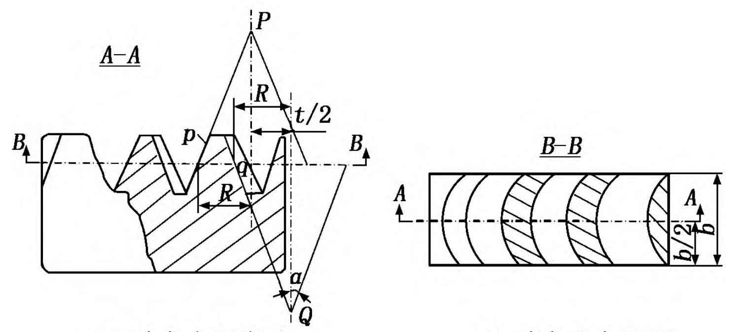
In general, the study of helical cylindrical gears is based on the basic rack of helical cylindrical gears. Figure 1 shows the basic rack of a circular cylindrical gear, with p and q representing the convex and concave surfaces of the gear teeth, which are part of two conical bodies P and Q. R represents the radius of the conical body at the indexing circle, t/2 represents the distance between the two conical axes, b represents the width of the rack, A-A represents the middle section of the rack, B-B represents the indexing plane of the rack, and the rack at section A-A has an involute tooth shape. Research has found that the tooth profile of a curved cylindrical gear in the middle section of the gear teeth is the same as that of an involute straight cylindrical gear. Therefore, the design and calculation of a curved cylindrical gear can refer to an involute straight cylindrical gear, and its basic geometric parameters are modulus m, number of teeth z, and pressure angle α、 The tooth top height coefficient h * a and top clearance coefficient c * are calculated using the same geometric dimensions as involute spur cylindrical gears. The calculation formula is shown in Table 1.
| Name | Calculation formula |
| Module m (mm) | Determined based on strength calculation |
| Number of teeth z | Zmin ≤ z1, z2=iz1, z1 is the number of small gear teeth, z2 is the number of large gear teeth, and i is the transmission ratio |
| pressure angle α (°) | The pressure angle of the central section is generally taken as α= 20 ° |
| Tooth top height coefficient h * a | Generally, h * a=1.0 |
| Top clearance coefficient c * | Generally, c *=0.25 |
| Dividing circle diameter d (mm) | D=mz |
| Tooth top height h a (mm) | Ha=h * am |
| Root height h f (mm) | Hf=(h * a+c *) m |
| Full tooth height h (mm) | H=ha+hf=(2h * a+c *) m |
| Tooth tip circle diameter da (mm) | Da=d+2ha=(2h * a+z) m |
| Root circle diameter df (mm) | df=d-2hf=(z-2h*a -2c* )m |
The design process of curved cylindrical gears can refer to involute straight cylindrical gears, and the design criteria are the same as those of straight cylindrical gears. In the design process of spur cylindrical gears, the main failure forms of gears are tooth surface fatigue pitting and tooth fatigue fracture. Therefore, according to the different application scenarios of gear transmission, design calculation criteria for tooth surface contact fatigue strength or tooth root bending fatigue strength can be selected for design calculation. Therefore, in the design and calculation process of spiral tooth cylindrical gears, reference can be made to the design and calculation process of involute straight tooth cylindrical gears. Firstly, the gear material, heat treatment method, and accuracy level can be selected, and then the corresponding design criteria can be determined based on the operating conditions. Through calculation, the number of teeth and modulus of the small gear can be determined. Due to the small number of teeth in the small gear, considering the problem of undercutting, the number of teeth in the small gear should be selected to meet the requirements of zmin ≤ z1; Once the number of teeth of the small gear is determined, the number of teeth of the large gear can be determined based on the gear transmission ratio, i.e. z2=iz1; Then, based on the geometric dimension calculation formula in Table 1, calculate the main dimensions of the spiral tooth cylindrical gear; Finally, the strength of the spiral cylindrical gear can be verified.
2.Cutting machining of spiral bevel gears
2.1 Cutting method for spiral bevel gears
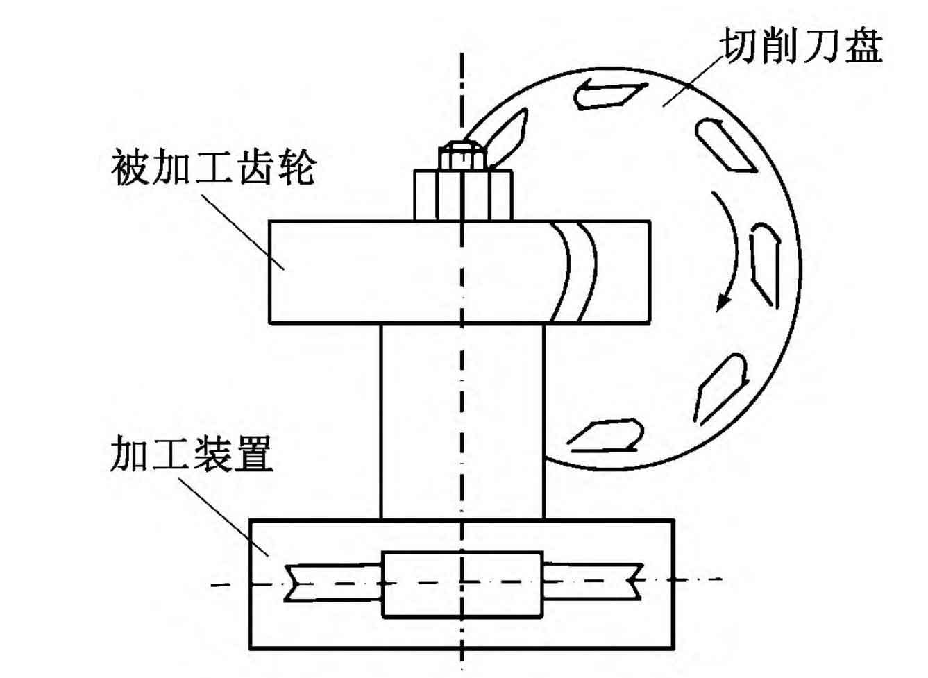
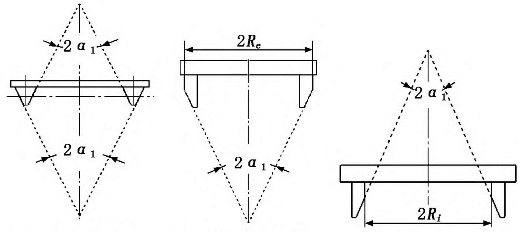
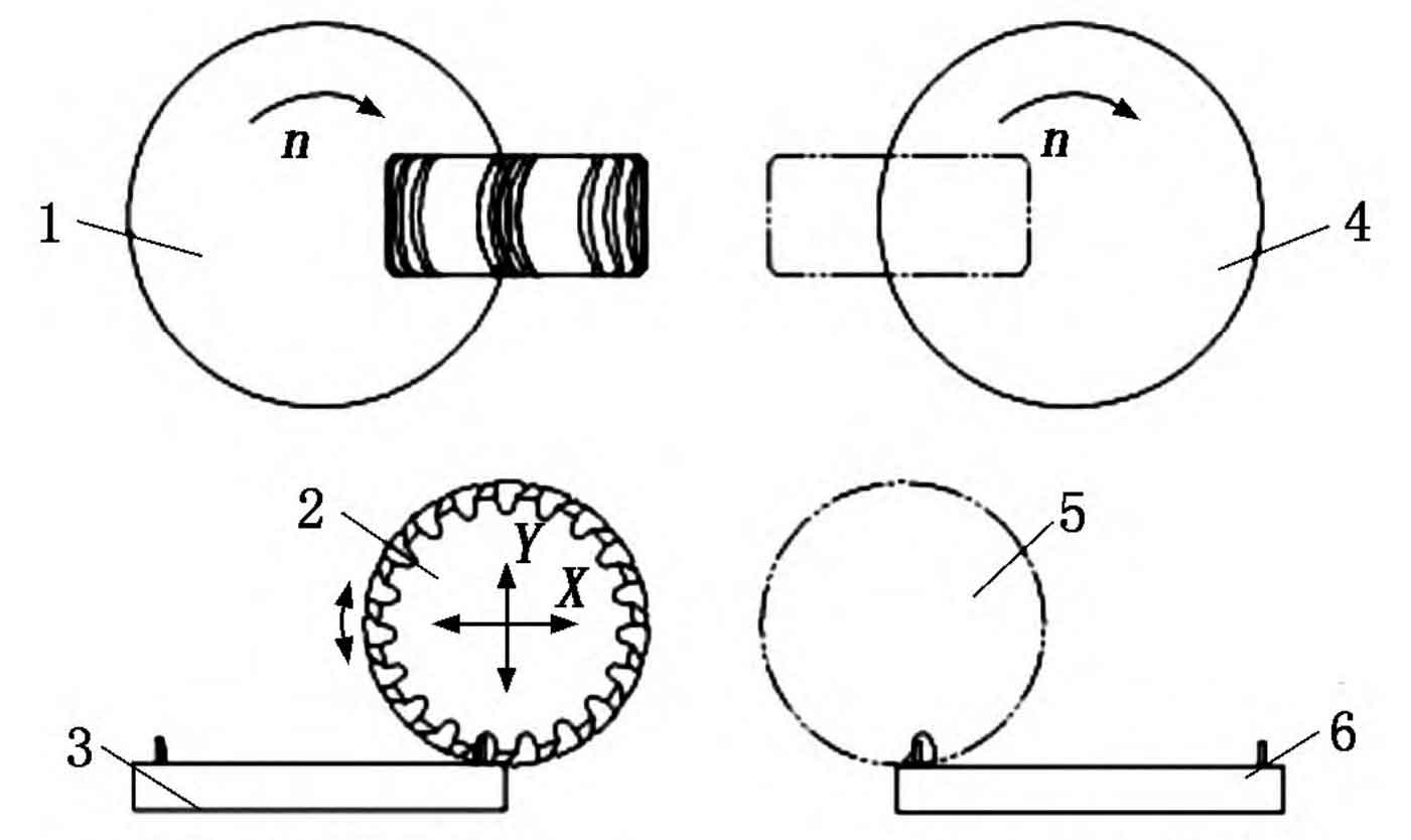
The cutting process of spiral bevel gears is different from that of straight cylindrical gears. Currently, the most typical cutting methods include the rotating cutter head method and the parallel connecting rod method. Due to the high efficiency and easy implementation of the rotating cutter head method in the tooth cutting process, this method is widely used in the cutting of spiral bevel gears, and its principle is shown in Figure 2. When using the rotating cutterhead method to cut curved cylindrical gears, there is an accurate generative motion relationship between the cutting cutterhead and the gear blank, that is, the pitch circle velocity of the processed gear blank is equal to the pitch circle velocity of the cutting cutterhead. In the process of cutting arc gear teeth, the cutting cutter head not only rotates the main motion, but also cuts into the feed motion along the radial direction of the tooth blank. When using the generative method for machining, because only one tooth groove can be cut at a time, precise indexing of the tooth blank must be controlled after each tooth groove is cut, and then the second tooth groove can be cut. After all the tooth grooves are cut in sequence, the machining of the arc gear can be completed. In theory, the groove of a spiral tooth cylindrical gear can be cut into a complete groove at once using a double-sided cutting tool, forming the convex and concave surfaces of the gear teeth. However, due to the full cutting edge of the double-sided cutting tool during the tooth cutting process, the cutting amount is large, the tool wear is fast, and the accuracy of the cut tooth surface is not high. It is difficult to cut a spiral gear that meets the requirements in actual tooth cutting. Therefore, based on the practice of using double-sided cutting tools for gear cutting, a single sided cutting tool for gear cutting is proposed. The cutting tool for spiral bevel gears is shown in Figure 3. In Figure 3, Re and Ri are the radii of the inner and outer single-sided cutting tool discs, respectively, α 1 is the tool pressure angle. Based on the practical experience of cutting teeth with double-sided cutting tools, in the process of cutting the grooves of arc gears, the double-sided cutting tools can be used to roughly cut the grooves, and then the single sided cutting tools can be used to precisely cut the convex and concave surfaces of the arc cylindrical gears to ensure the cutting accuracy.
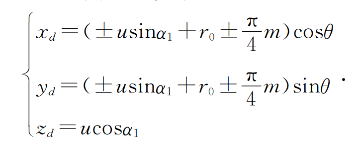
The advantage of using single-sided cutting tools to accurately cut the convex and concave surfaces of spiral bevel cylindrical gears is that the inner and outer single-sided cutting tools can be designed as tools with equal radii, resulting in higher accuracy in cutting the convex and concave surfaces of the gear teeth. However, due to the need for separate cutting of convex and concave surfaces, it is necessary to consider the installation of gear blanks and tool replacement during the machining process. Once the tool needs to be replaced or disassembled or installed during the machining process, it will inevitably affect the machining accuracy of the gear teeth. To this end, a single sided double milling machining method for spiral tooth cylindrical gears is proposed, and its machining principle is shown in Figure 4. During the cutting process of spiral tooth cylindrical gear teeth, two workstations are designed on a dedicated milling machine to cut the convex and concave surfaces of the gear teeth respectively. In Figure 4, 1 and 4 respectively represent convex and concave single edge milling cutters located on the left and right workstations, 2 and 5 respectively represent the machined spiral cylindrical gear blanks when milling convex and concave tooth surfaces, and 3 and 6 respectively represent convex and concave single edge milling cutters. From this, it can be seen that the cutting process of spiral bevel gears requires specialized CNC milling equipment to complete.
2.2 Tooth surface equation of arc tooth cylindrical gear cutting tool
In the process of milling spiral bevel gears, the milling tool is a specialized tool. To design and manufacture specialized gear milling tools, the tooth surface equation of the gear cutting tool can be established based on the principle of rotating cutter head method for gear cutting processing. Figure 5 shows the coordinate system between the cutting tool and the processed gear. Firstly, establish the coordinate system [O1, x1, y1, z1] to be fixedly connected to the processed gear blank, and the coordinate system [Od, xd, yd, zd] to be fixedly connected to the milling cutter disc, which rotates with the processed gear blank and milling cutter disc respectively; Then establish a fixed coordinate system [O, x, y, z], [O1, x10, y10, z10] as auxiliary coordinate systems. If the pitch radius of the gear blank is R1 and the average radius of the milling cutter is r0, the inner edge radius of the milling cutter is r0- π m/4, and the outer edge radius is r0+π m/4. In addition, in Figure 5, ω and ω 1 is the angular velocity of the tool and the tooth blank, φ 1 is the rotation angle of the gear blank. From this, it can be seen that in the coordinate system [Od, xd, yzd] fixed to the tool, the parameter equation of the tool surface can be established as follows:
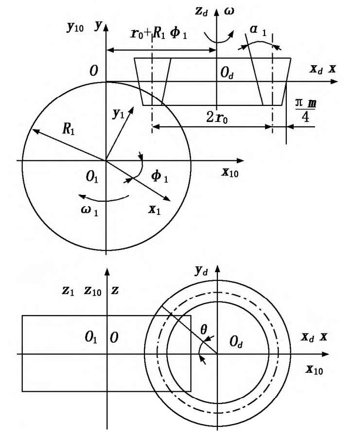
Where: u is the distance between the point on the tool surface along the generatrix of the conical surface and the reference point; θ The angle of the tool holder from the central section of the gear blank to the end face.
3.Cutting process and macro programming of spiral bevel gears
Based on the analysis of the tooth cutting process mentioned above, the tooth cutting process of the spiral cylindrical gear can be divided into three steps: the first step is to cut in the middle of the tooth groove of the spiral cylindrical gear, use a three sided edge tooth groove milling cutter to mill out the tooth groove, and cut off most of the tooth blank material; The second and third steps use a single edge cutting tool to machine the concave and convex tooth surfaces of the spiral cylindrical gear. When machining on a specialized gear milling machine tool, the indexing of the machining process is programmed using two methods: absolute indexing and relative indexing. For example, gears are indexed according to the number of teeth, and the indexing angle is δ, The first step from the starting angle of the machining program is to δ/ Starting from 2 places, that is, rough machining the tooth groove from the middle of the gear tooth groove; Step 2: From δ= Starting from 0, the third step starts from δ Start cutting at and use two single-sided cutting tools to process the corresponding concave and convex tooth surfaces; After each cutting tool completes the entire groove and tooth shape machining of the gear for one week, the machining of the entire arc tooth cylindrical gear can be completed. Due to the fact that the cutting tool enters according to the involute, the cutting path of the tool enters according to the involute. For example, the basic parameters for machining curved cylindrical gears are as follows: modulus m=3mm, number of teeth z=25, coefficient of tooth top height h * a=1.0, coefficient of top clearance c *=0.25. A macro program for tooth groove cutting cycle is developed as follows:
N10R1=3/m modulus
N20R2=25/z number of teeth
N30R3=R1 * R2/2/d graduation circle diameter
N40R4=1/ha tooth top height coefficient
N50R41=0.25/tooth top coefficient
N60R42=0/modification coefficient
N70R5=1/tooth root height coefficient
N80R6=R3/2+R4 * R1/tooth tip radius
N90R7=R3/2-R4 * R1/Root circle radius
N100R8=1/t involute opening initial value 0-1 reduction
N110R9=0/t increment
N120R10=60 * R8/ α Value
N130R11=3600/R2/indexing angle per tooth 3600/R2
N140R12=0/R12=A Gear rotation angle A=R10
atan (pi * R2 * R10/180)/R2)
N150R13=R3 * cos (R10)+pi * R3 * R10/180 * sin (R10)/
R13=X assignment
N160R14=R6+5/Start position of the tool in the X feed direction
N170G90G54G0A0X=R14/The workpiece quickly rotates to A0, and the tool moves quickly
Move to 5mm from the top of the tooth
AA:
N180G01X=R13A0F300/Move to start point
N190R8=R8-0.002/R8 assignment
N200R10=60 * R8/ α Angle value
N210G01X=R3 * cos (R10)+pi * R3 * R10/180 * sin (R10) A
=R10 atan (pi * R2 * R10/180)/R2) F300/Motion point X, A
N220IFR8 > 0GOTOAA/cycle
N222BB:/BB cycle
N230R9=R9-0.002
N240R101=60 * R9/R101 reverse movement
N250G01X=R3 * cos (R101)+pi * R3 * R101/180 * sin (R101)
A=R101 atan ((pi * R2 * R101/180)/R2) F600/reverse rotation return
N260IFR9 < 1GOTOBB
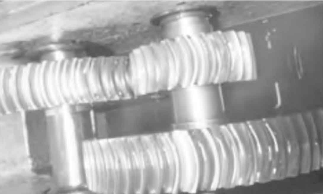
The milling program for spiral bevel gears feeds in the involute direction, and the tool retraction also retracts in the involute direction. When the tool moves along the involute direction, attention should be paid to avoiding over cutting the unprocessed tooth surface, in order to ensure sufficient machining allowance for the surface to be machined and ensure the machining quality of the arc tooth surface. Figure 6 shows the arc tooth cylindrical gear obtained through trial cutting. After meshing transmission inspection, it has been proven that the cut arc tooth cylindrical gear meets the expected requirements.