
In the field of mechanical transmission, arc cylindrical worm gears are widely recognized for their high transmission ratios, strong load-carrying capacity, high efficiency, and long service life. In my research, I have focused on the design and optimization of these worm gears using MATLAB’s computational and graphical capabilities. The objective is to develop a systematic approach that not only facilitates conventional design but also achieves an optimized solution through mathematical programming. This article presents my work on developing a conventional design module with the MATLAB GUIDE toolbox, formulating the optimization problem, and solving it with both gradient-based and heuristic algorithms.
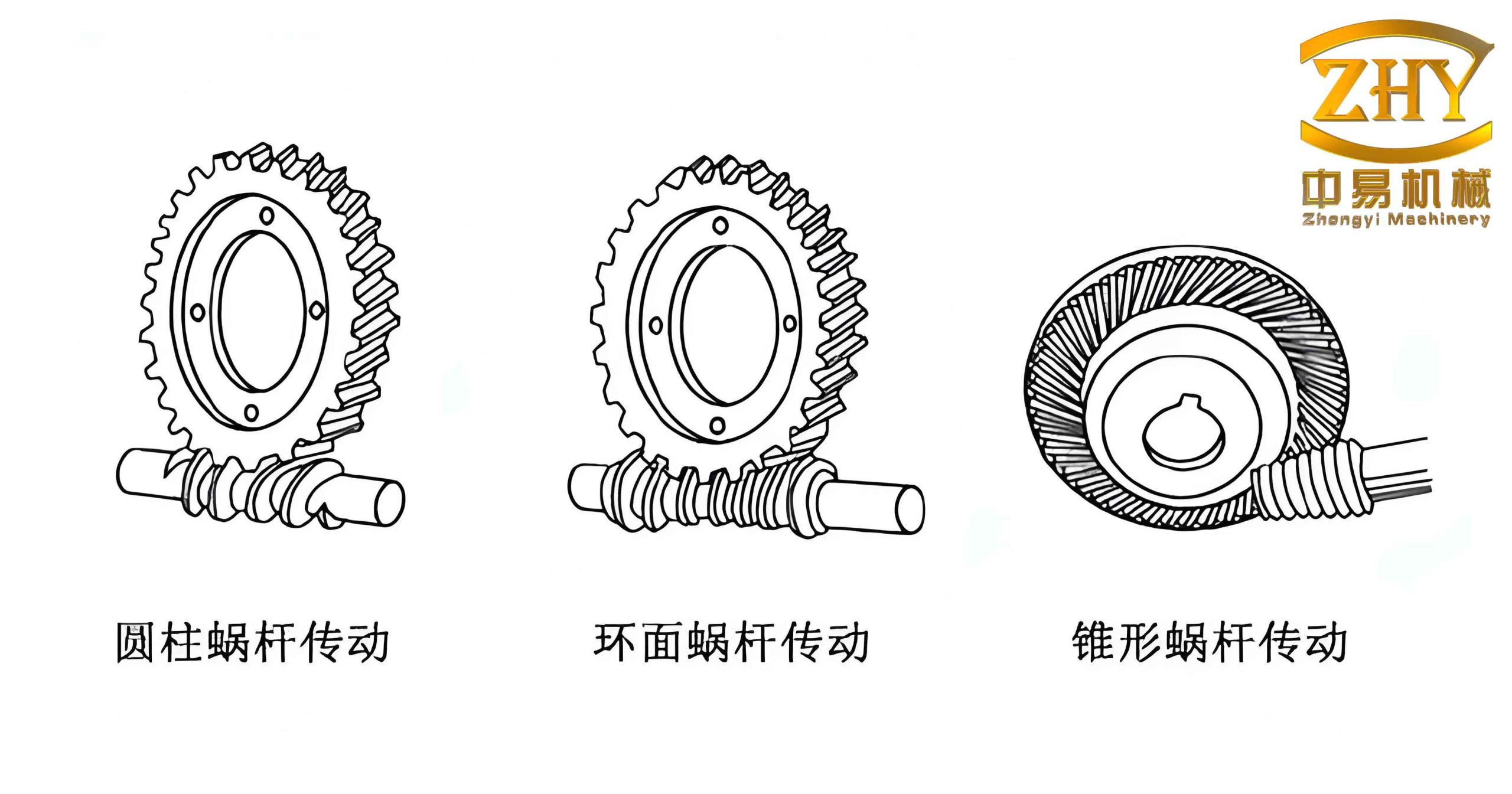
Conventional Design of Arc Cylindrical Worm Gears
The conventional design of worm gears involves a series of standards and empirical formulas. Using the MATLAB GUIDE toolbox, I developed a user-friendly interface that allows the input of design conditions such as input power, rotational speed, transmission ratio, and service life. The module automatically queries or interpolates necessary coefficients, performs strength and rigidity checks, and outputs key geometric parameters. For example, consider a specific design case: input power P1 = 55 kW, worm speed n1 = 1000 r/min, transmission ratio i = 10, closed drive with steady load, required life 10,000 hours. The worm material is 35CrMo (surface hardened 45–55 HRC, ground teeth), and the worm wheel rim is ZCuSn10P1 with a hub of HT100. The conventional design results are summarized in Table 1.
| Parameter | Symbol | Value | Unit |
|---|---|---|---|
| Center distance | a | 250 | mm |
| Module | m | 12.5 | mm |
| Number of worm threads | z1 | 3 | – |
| Number of worm wheel teeth | z2 | 31 | – |
| Worm pitch circle diameter | d1 | 105 | mm |
| Diameter coefficient | q | 8.4 | – |
Formulation of the Optimization Objective Function
After establishing a feasible conventional design, I proceeded to optimize the worm gear transmission. The optimization aims to reduce material cost and compactness while satisfying all strength and rigidity constraints. Three sub-objectives were considered: (1) minimization of the center distance a; (2) minimization of the total volume of the worm and worm wheel (approximated by the cylindrical volume at the pitch circle); (3) minimization of the worm wheel rim volume (since the rim is made of expensive bronze). I combined these into a single weighted objective function:
$$ \min F(\mathbf{x}) = \omega_1 f_1(\mathbf{x}) + \omega_2 f_2(\mathbf{x}) + \omega_3 f_3(\mathbf{x}) $$
where the weights are chosen as ω1 = 0.25, ω2 = 0.25, ω3 = 0.50, giving higher importance to reducing the costly rim volume.
The three sub-objectives are defined mathematically as:
$$ f_1(\mathbf{x}) = a = \frac{d_1 + d_2}{2} = \frac{m q + m z_2}{2} = \frac{m(q + i z_1)}{2} $$
$$ f_2(\mathbf{x}) = V_1 = \frac{\pi d_1^2 b_1}{4} + \frac{\pi d_2^2 b_2}{4} $$
where b1 is the worm face width: \( b_1 = 2.5 m \sqrt{z_2 + 2 + 2 x_b} \) (xb is the profile shift coefficient), and b2 is the wheel face width: \( b_2 = 0.45(d_1 + 6m) \).
$$ f_3(\mathbf{x}) = V_2 = \frac{\pi (d_e^2 – d_0^2) b_2}{4} $$
with de = d2 + 3m (tip circle diameter of wheel) and d0 = d2 – 6.4m (inner diameter of rim).
The design variables are chosen as:
$$ \mathbf{x} = [x_1, x_2, x_3]^{\mathrm{T}} = [m, z_1, q]^{\mathrm{T}} $$
Optimization Constraints
Boundary Constraints
Based on the conventional design and standard ranges, I imposed the following lower and upper bounds:
| Variable | Lower bound | Upper bound | Constraint expression |
|---|---|---|---|
| Module m (mm) | 6.5 | 16 | g(1) = 6.5 – x1 ≤ 0; g(2) = x1 – 16 ≤ 0 |
| Number of worm threads z1 | 2 | 6 | g(3) = 2 – x2 ≤ 0; g(4) = x2 – 6 ≤ 0 |
| Diameter coefficient q | 6 | 14 | g(5) = 6 – x3 ≤ 0; g(6) = x3 – 14 ≤ 0 |
Performance Constraints
Efficiency constraint: The total efficiency η = η1 η2 η3 should be at least 0.85. The meshing efficiency η1 is given by:
$$ \eta_1 = \frac{\tan \gamma}{\tan(\gamma + \varphi_v)} $$
where the lead angle γ satisfies \(\tan\gamma = z_1 / q\), and the equivalent friction angle φv is determined from the friction coefficient fv. I fitted the sliding speed vs with a power law: \( f_v = 0.046 / v_s^{0.4503} \). Thus:
$$ g(7) = 0.85 – 0.9506 \cdot \frac{\tan\gamma}{\tan(\gamma + \varphi_v)} \leq 0 $$
where the factor 0.9506 accounts for the product of bearing and oil churning efficiencies (η2 = 0.97, η3 = 0.98).
Contact fatigue strength constraint: The safety factor SH must be at least 2:
$$ S_H = \frac{\sigma_{H\lim}}{\sigma_H} \geq 2 \quad \Rightarrow \quad g(8) = 2 – \frac{\sigma_{H\lim}}{\sigma_H} \leq 0 $$
where σH is the computed contact stress and σHlim is the allowable contact stress of the wheel material.
Bending fatigue strength constraint: The safety factor SF must be at least 1.2:
$$ S_F = \frac{\sigma_{F\lim}}{\sigma_{F\max}} \geq 1.2 \quad \Rightarrow \quad g(9) = 1.2 – \frac{\sigma_{F\lim}}{\sigma_{F\max}} \leq 0 $$
Rigidity constraint: The maximum deflection of the worm shaft y must not exceed the allowable deflection [y]:
$$ y = \sqrt{F_{t1}^2 + F_{r1}^2} \cdot \frac{L^3}{48 E I} \leq [y] \quad \Rightarrow \quad g(10) = y – [y] \leq 0 $$
where L is the distance between supports, E is Young’s modulus, and I is the area moment of inertia of the worm shaft.
Optimization Solution
I wrote two MATLAB functions: the objective function goal_1.m and the constraint function subject_1.m. The built-in solver fmincon (interior-point algorithm) was employed. Additionally, to avoid local minima and compare results, I applied the particle swarm optimization (PSO) algorithm. The solutions obtained are:
- fmincon result: \(\mathbf{x}_1 = [10.1573, 3.8239, 8.5886]\)
- PSO result: \(\mathbf{x}_2 = [10.2177, 3.7891, 8.5389]\)
Both solutions are very close. For practical manufacturing, the variables were rounded to standard values: module m = 10 mm, number of worm threads z1 = 4, diameter coefficient q = 9. The rounded values were checked against all constraints and were satisfied. Table 3 compares the conventional design, the theoretical optimization results, and the practical optimized design.
| Design | m (mm) | z1 | q | a (mm) | V1 (mm3) | V2 (mm3) |
|---|---|---|---|---|---|---|
| Conventional | 12.5 | 3 | 8.4 | 250 | 1.1121×10⁷ | 5.4754×10⁶ |
| fmincon solution | 10.1573 | 3.8239 | 8.5886 | 237.8 | 8.8730×10⁶ | 3.7116×10⁶ |
| PSO solution | 10.2177 | 3.7891 | 8.5389 | 237.2 | 8.8440×10⁶ | 3.7295×10⁶ |
| Optimized (rounded) | 10 | 4 | 9 | 245 (or 250)* | 9.5528×10⁶ | 3.8172×10⁶ |
*The center distance after rounding becomes 245 mm, but because standard center distances are often preferred (250 mm), one can keep a = 250 mm and adjust the profile shift coefficient to xb = 0.5. The resulting volumes still show significant reduction: total volume decreased by about 14% and rim volume decreased by about 30% compared with the conventional design.
Discussion of Optimization Results
The optimization demonstrates that substantial material savings are achievable without violating strength or rigidity requirements. The use of MATLAB both for conventional design (via GUIDE) and for optimization (via fmincon and PSO) provided an integrated workflow. The conventional design module allowed quick parameter retrieval and verification, while the optimization routine systematically searched the design space. The fact that two different algorithms yielded nearly identical solutions confirms the robustness of the optimum.
It is worth noting that the efficiency constraint played an important role. In the conventional design with z1 = 3 and q = 8.4, the lead angle γ = arctan(3/8.4) ≈ 19.65°, giving good efficiency. In the optimized design with z1 = 4 and q = 9, γ = arctan(4/9) ≈ 24.0°, which further improves efficiency (meshing efficiency rises). The constraint g(7) was active in the optimization, indicating that the optimum lies on the boundary of allowable efficiency. By increasing the lead angle, the transmission becomes more efficient, but the worm wheel diameter reduces, leading to lower sliding speeds and acceptable friction.
Conclusion
In this work, I developed a MATLAB-based tool for the conventional design of arc cylindrical worm gears using the GUIDE toolbox. The tool accelerates the design process by automating coefficient lookup, interpolation, and strength calculations. Building on the conventional design, I formulated a multi-objective optimization problem with center distance, total volume, and worm wheel rim volume as objectives, subject to boundary and performance constraints (efficiency, contact strength, bending strength, and rigidity). The optimization was solved using both gradient-based (fmincon) and heuristic (PSO) algorithms. The results showed that an optimized design with m = 10 mm, z1 = 4, and q = 9 reduced the worm wheel rim volume by approximately 30% compared to the conventional design, while maintaining all required safety factors. This demonstrates the effectiveness of the proposed optimization methodology for worm gears.
The developed approach can be easily extended to other types of worm gears by adjusting the objective functions and constraints. Future work may include consideration of thermal constraints, dynamic loads, and multi‑stage transmissions. The integration of conventional design and optimization within a single MATLAB environment provides a powerful tool for engineers working with worm gears.