
I investigated a repeatable hydraulic stop on an imported high-precision CNC universal gear shaping machine after approximately four hours of continuous gear shaping. The machine is used for internal and external gear shaping and is capable of machining straight teeth, helical teeth, and herringbone teeth. Because the gear shaping operation is a core process, any unplanned stop has a direct effect on production flow, part quality, and operator confidence. The failure appeared as an alarm on the cam travel function, followed by a complete stop of the hydraulic system. After the alarm was cleared and the hydraulic system was restarted, the machine could run again, but the same condition returned after a similar period of gear shaping. This paper records my diagnostic reasoning, the measurements I made, the PLC signal tracing I performed, and the corrective action that eliminated the fault.
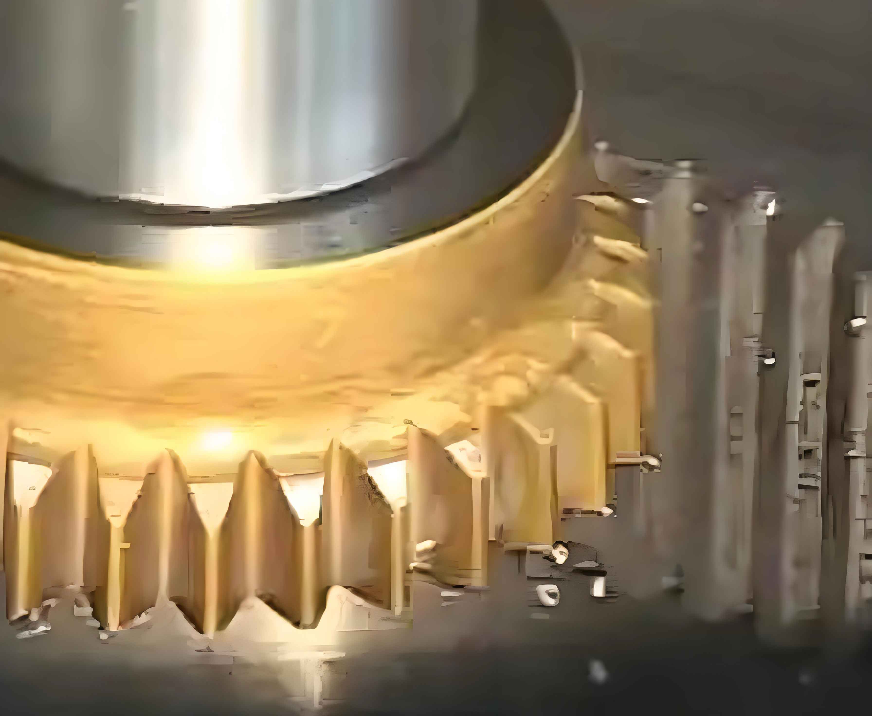
The machine is a German-origin high-precision CNC gear shaping machine equipped with a LIEBHERR CNC system and INDRAMAT servo amplifiers. It has seven axes, identified as X1, Z1, Z2, Z3, C1, C2, and B4. Among these, X1, Z3, and B4 are working axes. Z3 is the main drive axis and uses an INDRAMAT servo motor. B4 performs the relief motion and is synchronized with the Z3 axis. The maximum workpiece diameter is 1000 mm. The machine is heavily loaded in production, and the gear shaping cycle is long and repetitive. Therefore, a fault that appears after several hours of gear shaping must be treated as a systematic condition rather than a random event.
Machine Context and Failure Signature
I began by establishing the exact failure signature. The machine was machining internal teeth when the alarm appeared. The alarm text was “F77 Fault, cam travel.” At that moment, the hydraulic system stopped completely. The machine could not continue the gear shaping cycle. When the operator cleared F77 and restarted the hydraulic system, the machine resumed operation. However, after approximately four hours of gear shaping, the same alarm and hydraulic stop occurred again. This repetition was the most important diagnostic clue because it connected the fault to a time-dependent or load-dependent condition.
I recorded the operational behavior over a twelve-hour monitoring period. During normal gear shaping, the hydraulic pressure was stable at approximately 60 bar, which met the technical requirement. The cam travel monitoring switches also behaved normally during manual checks and during initial production monitoring. This preliminary evidence made a gross hydraulic pump failure unlikely. Instead, I focused on the interaction between the cam travel detection circuit, the clamp pressure monitoring circuit, the PLC alarm logic, and the hydraulic pump enable logic.
| Item | Observed condition | Diagnostic significance |
|---|---|---|
| Machine type | CNC universal gear shaping machine | Gear shaping process with internal and external tooth capability |
| Control system | LIEBHERR CNC with INDRAMAT servo amplifiers | PLC-based alarm and interlock tracing is possible |
| Working axes | X1, Z3, B4 | Z3 is the main gear shaping drive; B4 is synchronized relief motion |
| Maximum workpiece diameter | 1000 mm | Large workpiece inertia and long gear shaping cycles increase thermal and hydraulic loading |
| Normal hydraulic pressure | Approximately 60 bar | Initial pump condition appeared acceptable |
| Failure interval | Approximately 4 h of continuous gear shaping | Time-dependent drift or thermal effect is strongly indicated |
| Alarm | F77 Fault, cam travel | Cam travel monitoring or its enabling conditions were involved |
| Response after clearing | Machine restarted and ran normally | The fault was not a permanent wiring break or hard component failure |
The repeating four-hour pattern was consistent with a pressure switch or hydraulic path that changed slowly during gear shaping. A hard failure would normally appear immediately. A loose connector would normally be sensitive to vibration rather than a regular time interval. A thermal drift in a pressure switch, or a slow pressure change in a preload circuit, could produce a signal loss after the machine reached a stable thermal state. I therefore defined the normal hydraulic condition as a band rather than a single value:
$$P_{hyd}(t) \in [P_{min},P_{max}]=[58,62]\ \text{bar}$$
and I treated any pressure monitoring signal that crossed its switching threshold during gear shaping as a candidate cause. The key question was whether the F77 alarm caused the hydraulic stop or whether the hydraulic stop caused the F77 alarm. If I could answer that question, the search space would be reduced considerably.
Diagnostic Strategy and Initial Hypotheses
My first-person diagnostic approach was to separate the fault into four domains: mechanical cam movement, electrical detection, hydraulic pressure and flow, and PLC logic. I did not replace parts at random. I used the alarm message, the hydraulic response, and the PLC graphical program as evidence. I also used the principle that a valid root-cause candidate must explain the complete sequence: normal gear shaping for about four hours, F77 alarm, hydraulic stop, successful restart, and repeatability.
| Hypothesis | Expected evidence | Initial test | Initial conclusion |
|---|---|---|---|
| Cam detection switch misalignment | B72.13, B72.14, or B72.15 signal missing during switching | Manual internal and external switching and signal monitoring | No abnormality found |
| Cam clamp pressure switch failure | F721 signal loss causes clamp alarm and possibly stop | Disconnect F721 during dry gear shaping | F721 caused a clamp alarm but did not stop hydraulics |
| Cam locking mechanism fault | E22.6 or E22.7 abnormal; lock pressure unstable | Monitor E22.6, E22.7, and F673 pressure | Signals normal at 60 bar |
| Hydraulic pump command fault | Q52.0 drops; F131.0 reset; F131.2 set | Trace PLC logic for M27 | One logic path impossible; another path required further trace |
| Pressure switch drift | One of F72.21 to F72.24 fluctuates after hours | Long-duration no-load monitoring | F72.21 fluctuated between 31 and 25.5 bar |
| Internal preload line leakage or blockage | Pressure change not reproducible after sensor swap | Control-variable swap of switch bodies | Fault followed the switch, not the hydraulic line |
I also established a simple evidence rule for the gear shaping machine. A candidate cause was acceptable only if it satisfied the following relationship:
$$H_{candidate}\Rightarrow \left(A_{F77}\land H_{stop}\land R_{restart}\land T_{repeat}\right)$$
Here, \(A_{F77}\) is the cam travel alarm, \(H_{stop}\) is the hydraulic stop, \(R_{restart}\) is successful restart after clearing, and \(T_{repeat}\) is the approximately four-hour repeat interval. A cause that explained only one symptom was not considered sufficient. This rule prevented me from stopping at the cam switch itself merely because the alarm text contained the words “cam travel.”
Cam Travel Monitoring and Clamp Circuit Investigation
I opened the side sealing cover of the gear shaping cutter shaft and inspected the cam travel detection arrangement. There are three proximity detection switches and one circular detection block. The three switches are B72.13, B72.14, and B72.15. B72.13 monitors the left side of the cam, which corresponds to internal tooth gear shaping. B72.14 monitors the middle position of the cam. B72.15 monitors the right side of the cam, which corresponds to external tooth gear shaping. I performed manual internal and external tooth switching and monitored all three signals. I found no abnormal signal, no loose detection block, and no position where the switch failed to detect the block during the switching stroke.
| Detection switch | Cam position | Gear shaping mode | Observed condition |
|---|---|---|---|
| B72.13 | Left side | Internal tooth gear shaping | Signal present at left position; no loss during manual switching |
| B72.14 | Middle position | Transition monitor | Signal present at middle position; no abnormal behavior |
| B72.15 | Right side | External tooth gear shaping | Signal present at right position; no abnormal behavior |
| Detection block | Cam reference | All cam travel modes | No looseness or visible damage |
I then investigated the cam clamping circuit. The machine has a pressure detection switch F721 used mainly for cam clamping. To determine whether F721 could produce the observed stop, I switched off the coolant in the program, raised the Z2 axis by 100 mm, and performed dry gear shaping. During this dry gear shaping, I deliberately disconnected the signal line of F721. The machine produced a cam clamping alarm, but the hydraulic system did not stop. This test was important because it separated a clamp alarm from a hydraulic stop. It showed that F721 was not the cause of the complete hydraulic shutdown, even though it could generate an alarm.
| Test condition | Action | Machine response | Interpretation |
|---|---|---|---|
| Dry gear shaping with coolant off and Z2 raised 100 mm | Disconnect F721 signal line | Cam clamping alarm appeared; hydraulic system remained running | F721 is not the hydraulic stop trigger |
| Normal gear shaping | Monitor F721 | Pressure remained at approximately 60 bar | Clamp pressure was stable at the time of observation |
| Normal gear shaping | Monitor E22.6 and E22.7 | Locking and release signals normal | Locking mechanism feedback was plausible |
Next, I examined the cam drive hydraulic circuit. The internal and external tooth cam switching is performed mainly by solenoid valve Y755. The sequence is as follows. First, the a-side of solenoid valve Y753 is energized to open the locking mechanism. This locking mechanism locks the motor housing sleeve to prevent clearance during motion. The valve has a self-locking function, so after momentary energization, the a-side of Y753 is de-energized and remains self-held. Then the a-side of Y755 is energized. Hydraulic oil passes through Y755 into the cylinder and pushes the piston to the left. This implements the internal tooth gear shaping cam switch. When the position is reached, detection switch B72.13 detects the signal. The cylinder body is connected to the machine body, and the piston rod is connected to the drive motor through a coupling. When the piston moves left, the drive motor moves left accordingly. After the detection position is reached, the b-side of Y753 is energized to lock the mechanism. This valve also has a self-locking function, so after momentary energization, the b-side of Y753 is de-energized and remains self-held. Finally, Y755 is de-energized and remains in the middle position.
| Step | Valve state | Hydraulic action | Mechanical result | Feedback |
|---|---|---|---|---|
| 1 | Y753 a-side energized momentarily | Unlock oil path opened | Motor housing sleeve unlocked | Lock release condition established |
| 2 | Y755 a-side energized | Oil flows to cylinder | Piston and motor move left for internal tooth cam | B72.13 detects left position |
| 3 | Y753 b-side energized momentarily | Lock oil path opened | Locking mechanism closes | Lock feedback established |
| 4 | Y755 de-energized | Valve returns to center | Cam remains in selected position | Normal gear shaping continues |
I checked the detection switches and the detection block again during internal and external switching and during trial gear shaping. I found no looseness, no intermittent detection, and no mechanical interference. I suspected the motor locking mechanism, but monitoring of F721 showed a stable pressure of 60 bar. I also checked the PLC signals E22.6 and E22.7. E22.6 is the locking signal, and E22.7 is the release signal. Both were normal. At that stage, the cam mechanism itself, the clamp switch F721, and the lock feedback signals did not explain the hydraulic stop during gear shaping.
PLC Alarm Logic and Causality Test
I then concentrated on the PLC logic for the F77 alarm. According to the machine PLC graphical documentation, the F77 alarm is generated mainly by an output at Q105.5. I traced the control rung for Q105.5. The most probable normal-operation input capable of causing the alarm was E22.6, the locking pressure detection signal. The critical question remained: did the hydraulic stop cause the alarm, or did the alarm cause the hydraulic stop? I needed a direct test rather than an assumption.
I located the actual pressure detection switch F673 corresponding to the E22.6 locking pressure signal. F673 displayed the same pressure as the hydraulic pump outlet, namely 60 bar. I checked the actual pressure with a gauge and confirmed 60 bar. I then disconnected the E22.6 signal. The machine produced the F77 Fault, cam travel alarm, but the hydraulic system did not stop. This result was decisive. It showed that loss of E22.6 alone could generate the alarm, but it could not stop the hydraulic pump. Therefore, the hydraulic stop observed during production was not caused by the F77 alarm. The F77 alarm was a consequence of the hydraulic stop. The direction of causality was:
$$H_{stop}\rightarrow A_{F77}$$
and not
$$A_{F77}\rightarrow H_{stop}.$$
| Test | Signal or component | Observed result | Causal conclusion |
|---|---|---|---|
| Monitor locking pressure | F673 and E22.6 | Approximately 60 bar; normal | Lock pressure was not low during observation |
| Disconnect E22.6 | Locking pressure feedback | F77 alarm appeared; hydraulic system continued running | F77 alone does not stop hydraulics |
| Observe production failure | F77 and hydraulic pump | Both alarm and hydraulic stop occurred | Hydraulic stop is the upstream event |
| Clear F77 and restart | Alarm and pump enable | Machine ran again for a similar period | Fault is a recoverable enabling-condition loss |
With the causality direction established, I traced the hydraulic motor M27 command. The output point for the hydraulic motor is Q52.0. From the PLC graphical logic, stopping the hydraulic pump requires F131.2 to have a signal and to reset F131.0. I followed the F131.2 control path. To make F131.2 have an output, T18 must receive a signal input, meaning T18 must be set to 1. I then followed the T18 control diagram. It appeared that F106.0 would need to be 1 for T176 to produce an output. However, when I inspected the F106.0 control graphic, I found that F106.0 could not produce a signal at all. The logic took F0.0 and combined its own signal with its inverted signal using an AND operation. The output of such a combination is always zero:
$$F106.0=F0.0\land\overline{F0.0}=0.$$
Therefore, that branch could not be the cause of the hydraulic pump stop. I continued with the F131.1 control signal. I inspected the F131.1 function block and found that when F131.1 has an output, its input signal is accompanied by other prompt information. I arranged for the operator to keep the machine condition unchanged when the alarm occurred and to record the prompt information. The prompt information corresponded to input control signal S149.6.
I traced S149.6 further. T214 controls the S149.6 signal output. T214 is controlled by four input signals: I23.0, I23.1, I23.2, and I23.3. These four inputs correspond to four pressure detection switches: F72.21, F72.22, F72.23, and F72.24. During normal operation, all four pressure detection switches worked correctly. The logical relationship can be summarized as:
$$S149.6=f(T214),\qquad T214=g(I23.0,I23.1,I23.2,I23.3).$$
If any one of these pressure feedback signals was lost intermittently, the T214 timing or logic could change, S149.6 could appear, F131.1 could be set, and the hydraulic pump could be stopped. That would explain the F77 alarm as a downstream consequence. I therefore moved from static checks to long-duration dynamic monitoring during no-load gear shaping.
| PLC signal | Associated pressure switch | Normal function | Observed state during initial check |
|---|---|---|---|
| I23.0 | F72.21 | Pressure feedback input 1 | Normal before long-duration run |
| I23.1 | F72.22 | Pressure feedback input 2 | Normal before long-duration run |
| I23.2 | F72.23 | Pressure feedback input 3 | Normal before long-duration run |
| I23.3 | F72.24 | Pressure feedback input 4 | Normal before long-duration run |
| S149.6 | Derived from T214 | Prompt input associated with hydraulic stop condition | Appeared only when fault was reproduced |
| F131.1 | Hydraulic stop control | Contributes to stopping hydraulic pump | No stable abnormality before long-duration run |
I ran the machine without load and monitored these signals continuously. The monitoring was not a short check. I kept the gear shaping machine in a representative cycle condition and watched the pressure switch signals over several hours. After approximately four hours, F72.21 began to fluctuate significantly. The pressure varied between approximately 31 bar and 25.5 bar, back and forth. This fluctuation was sufficient to cause intermittent loss of I23.0. The intermittent loss of I23.0 then propagated through T214 and S149.6, producing the hydraulic stop condition and the associated F77 alarm. The fault was now localized to the F72.21 pressure detection branch.
I quantified the pressure stability condition as follows. For a stable switch, the measured pressure should remain above the switching threshold with a margin:
$$P_{F72.21}(t)\ge P_{threshold}+\Delta P_{margin}.$$
In the observed normal state, the pressure was near the system pressure of 60 bar. In the faulty state, the pressure fell into a band that crossed the switching threshold:
$$P_{F72.21}(t)\in[25.5,31]\ \text{bar}\quad\Rightarrow\quad I23.0(t)\ \text{became unstable}.$$
The variance of the measured pressure was also a useful indicator:
$$\sigma^2=\frac{1}{N}\sum_{i=1}^{N}\left(P_i-\bar{P}\right)^2.$$
A large variance after several hours of gear shaping indicated a time-dependent pressure signal problem. However, the variance alone did not prove whether the switch body or the hydraulic line was at fault. I therefore used a control-variable swap test.
Root-Cause Isolation by Control-Variable Swap
There were two possible explanations for the F72.21 fluctuation. The first was a hidden defect in the pressure switch itself. After long-term operation, the switch performance could degrade, causing unstable switching and incorrect output. The second was a leakage or blockage in the spindle internal preload pressure line. After long-term operation, the pressure in that line could change significantly. The second possibility would be much more complex to repair because it would involve the internal hydraulic path. I needed a method that could distinguish the two without replacing the entire hydraulic circuit or waiting for a spare part.
F72.21, F72.22, F72.23, and F72.24 are the same model of pressure detection switch. I therefore exchanged the bodies of F72.21 and F72.22 while keeping the signal wire positions unchanged. This is a control-variable method. If the fault followed the switch body, the originally healthy F72.22 channel would become unstable after the swap. If the fault remained on the original F72.21 channel, the hydraulic line or circuit would be implicated. I then continued no-load operation and monitored all four switch signals.
| Stage | F72.21 channel | F72.22 channel | Observation | Interpretation |
|---|---|---|---|---|
| Before swap | Original switch installed | Original switch installed | After about 4 h, F72.21 fluctuated between 31 and 25.5 bar | Fault localized to F72.21 branch |
| Swap switch bodies | F72.22 body installed | F72.21 body installed | Signal wires unchanged; machine run without load | Control-variable test started |
| After swap, about 3 h | No obvious change | Signal fluctuated strongly | Fault moved to F72.22 channel | Fault followed the switch body |
| Conclusion | Channel healthy | Original F72.21 body defective | Pressure line was not the root cause | Replace the defective pressure switch |
The swap result was clear. After approximately three hours of no-load operation, the F72.22 channel, which now contained the original F72.21 switch body, showed strong fluctuation. The F72.21 channel, which now contained the original F72.22 switch body, showed no obvious change. Therefore, the fault followed the switch body and not the hydraulic line. The root cause was the original F72.21 pressure detection switch itself.
I can represent the swap logic as a comparison of drift indicators. Let \(D_{21}\) be the drift indicator of the F72.21 channel and \(D_{22}\) be the drift indicator of the F72.22 channel. Before the swap:
$$D_{21}\gg D_{22}.$$
After exchanging the switch bodies while keeping the hydraulic connections and signal wires unchanged:
$$D_{21}\approx \text{small},\qquad D_{22}\gg D_{21}.$$
Because the drift moved with the switch body, the switch body was the root cause. This was a stronger conclusion than a simple pressure measurement because it separated the sensor from the hydraulic circuit.
I replaced the F72.21 pressure detection switch. After replacement, I ran the machine without load for ten hours and observed no fault. I then returned the machine to production. I monitored the gear shaping process for two days, and the fault did not recur. The repeatable four-hour hydraulic stop had been eliminated. The F77 alarm no longer appeared because the upstream pressure feedback instability was removed.
| Validation stage | Duration | Load condition | Result | Conclusion |
|---|---|---|---|---|
| No-load run after replacement | 10 h | No workpiece load | No fault | Immediate repair successful |
| Production run after replacement | 2 days | Normal gear shaping load | No F77 alarm and no hydraulic stop | Fault eliminated under production conditions |
| Signal monitoring after replacement | Continuous during validation | Gear shaping cycle | F72.21 signal stable | Pressure feedback path restored |
Why the Fault Appeared After Several Hours of Gear Shaping
The four-hour delay deserves explanation because it was the signature of the fault. A pressure switch can appear normal when the machine is cold or when the gear shaping cycle has just started. As the hydraulic system reaches thermal equilibrium, the internal clearance, seal behavior, and fluid viscosity change. A marginal switch can begin to leak internally or change its switching point. In addition, the gear shaping cycle applies repeated pressure pulses during cam locking, relief motion, and internal tooth machining. These pulses can produce a slow mechanical or hydraulic drift that is not visible in a short test.
I modeled the time-dependent condition as a drift term added to the nominal pressure:
$$P_{measured}(t)=P_{nominal}+\Delta P_{thermal}(t)+\Delta P_{switch}(t)+\Delta P_{load}(t).$$
In a healthy gear shaping machine, the sum of the drift terms remains within the allowable band. In the faulty condition, the switch drift term \(\Delta P_{switch}(t)\) increased after several hours and caused the measured pressure to cross the switching threshold. The repeat interval was therefore not a fixed timer but a consequence of thermal and load history. This is why the alarm sometimes appeared near four hours rather than at an exact minute.
The duty cycle of the gear shaping process can be expressed as:
$$D=\frac{T_{cutting}}{T_{cutting}+T_{indexing}+T_{switching}}.$$
For a long internal tooth gear shaping run, the cutting duty is high, and the hydraulic system remains under continuous load. The cam locking circuit is repeatedly pressurized and released. A pressure switch with degraded repeatability may pass a short test but fail after many cycles. The replacement switch restored the margin between the actual pressure and the switching threshold.
Corrective Action and Preventive Maintenance
The immediate corrective action was the replacement of the F72.21 pressure detection switch. However, I did not stop at replacement. I converted the diagnostic findings into preventive maintenance actions because the same switch family is used in other pressure monitoring positions. The gear shaping machine has multiple hydraulic interlocks, and a single unstable pressure switch can stop the entire gear shaping cycle. A planned inspection and monitoring routine is therefore justified.
| Action area | Recommended action | Frequency | Acceptance criterion |
|---|---|---|---|
| Pressure switch inspection | Check F72.21, F72.22, F72.23, and F72.24 signal stability during a long gear shaping run | Quarterly or after any repeat alarm | No unexplained fluctuation; signal remains above threshold with margin |
| Hydraulic pressure verification | Compare pump outlet pressure with each pressure switch indication | Monthly | Deviation within the specified tolerance around 60 bar |
| Cam detection check | Clean and verify B72.13, B72.14, and B72.15; check the detection block | Every scheduled maintenance | Stable signal at left, middle, and right positions |
| Clamp circuit check | Verify F721 response and locking signals E22.6 and E22.7 | Every scheduled maintenance | Clamp alarm does not produce unintended hydraulic stop |
| Valve response check | Verify Y753 and Y755 switching sequence and self-locking behavior | Semiannual | Correct internal and external tooth cam switching |
| PLC diagnostics | Archive the logic paths for F77, Q105.5, F131.1, F131.2, S149.6, and T214 | After any PLC change | Logic matches the validated machine documentation |
| Spare parts | Keep at least one matched pressure switch in stock | Continuous | Replacement available without extended gear shaping downtime |
I also recommend a simple operator response rule. When the F77 cam travel alarm appears during gear shaping, the operator should record the current tooth count and the exact machine state before clearing the alarm. This does not repair the machine, but it reduces the risk of scrapping a workpiece because the operator cannot determine the current gear tooth position after an unexpected stop. The maintenance team should then check whether the hydraulic system stopped before or after the alarm. If the hydraulic system stopped first, the pressure feedback and pump enable logic should be examined before replacing cam travel components.
| Alarm scenario | Observed sequence | First diagnostic direction |
|---|---|---|
| F77 appears while hydraulics remain on | Alarm first, no hydraulic stop | Check cam travel detection, clamp feedback, and F77 input logic |
| Hydraulics stop and F77 follows | Hydraulic stop first, alarm second | Check hydraulic pump enable, pressure switches, T214, S149.6, and F131.1 |
| F77 repeats after several hours of gear shaping | Time-dependent repeat | Monitor pressure switch drift and thermal effects during a long gear shaping run |
| F77 clears and machine restarts normally | Recoverable signal loss | Look for intermittent pressure feedback rather than a hard mechanical break |
For condition monitoring, I suggest calculating a simple stability index for each critical pressure switch during gear shaping:
$$S_i=\frac{P_{i,min}}{P_{threshold}}.$$
A value close to 1 or below 1 indicates insufficient margin. A practical warning limit should be established from the machine specification and the observed normal band. In this case, the faulty switch drove the pressure indication down into the mid-twenties to low-thirties bar range, which was far below the normal hydraulic pressure and clearly outside the stable band. A periodic trend check would have revealed the degradation before a production stop.
Discussion of PLC Tracing Practice
The PLC tracing was the most valuable part of this investigation. The alarm text alone pointed toward cam travel, but the PLC logic showed that the hydraulic stop was upstream of the alarm. I used the graphical PLC documentation to follow the output Q105.5, the pump output Q52.0, the stop logic involving F131.2 and F131.0, and the alternative stop path involving F131.1 and S149.6. The impossible Boolean branch involving F106.0 was also useful because it eliminated a false path. The relationship
$$F106.0=F0.0\land\overline{F0.0}=0$$
demonstrated that a branch that looked plausible at first could not produce a signal. This prevented unnecessary replacement of components on that path. I then followed the only remaining viable path to T214 and the four pressure switch inputs. The long-duration monitoring confirmed the intermittent input loss. This is a repeatable method for complex CNC gear shaping machines: identify the alarm output, trace the enabling conditions, test causality by disconnecting one signal at a time, and monitor the remaining candidates over a representative gear shaping cycle.
I also used a substitution method under limited spare availability. The machine had no spare pressure switch at the time. Rather than waiting for a new part, I exchanged two identical switch bodies and kept the hydraulic connections and signal wires unchanged. This is a valid control-variable method because it changes only the sensor body. The fault moved with the sensor body, which proved the sensor was defective. I then replaced the defective switch. This approach minimized downtime and avoided unnecessary work on the hydraulic lines.
Summary of the Diagnostic Chain
| Step | Question | Evidence | Conclusion |
|---|---|---|---|
| 1 | Is the hydraulic pressure generally stable? | Approximately 60 bar during 12 h monitoring | Gross pump failure unlikely |
| 2 | Are the cam detection switches faulty? | Manual switching and signal monitoring normal | Cam detection not the root cause |
| 3 | Is F721 the cause? | Disconnect test produced clamp alarm but no hydraulic stop | F721 not the hydraulic stop cause |
| 4 | Does F77 cause the hydraulic stop? | E22.6 disconnect produced F77 but hydraulics remained on | Hydraulic stop causes F77 |
| 5 | Which PLC path stops the pump? | F131.2 branch impossible; F131.1 branch led to S149.6 and T214 | Pressure feedback inputs I23.0 to I23.3 became the focus |
| 6 | Which pressure input is unstable? | F72.21 fluctuated between 31 and 25.5 bar after about 4 h | I23.0 intermittent loss was the trigger |
| 7 | Is the switch or the hydraulic line faulty? | Switch body swap moved the fault to the other channel | F72.21 switch body was defective |
| 8 | Is the repair effective? | 10 h no-load and 2 days production monitoring | Fault eliminated |
The root cause was a degraded F72.21 pressure detection switch that became unstable after several hours of gear shaping. The unstable pressure feedback caused intermittent loss of I23.0. That signal loss propagated through T214 and S149.6 to F131.1 and stopped the hydraulic pump. Once the hydraulic system stopped, the cam travel condition produced F77 Fault, cam travel. The alarm was therefore a downstream symptom, not the primary fault. Replacing the pressure switch restored the pressure feedback margin and eliminated the repeatable gear shaping interruption.
Conclusion
I resolved the hydraulic stop on the CNC universal gear shaping machine by combining alarm analysis, PLC logic tracing, controlled signal disconnection, long-duration pressure monitoring, and a switch-body swap test. The fault was not in the cam mechanism itself. It was not caused by the cam clamp switch F721. It was not a simple hydraulic pump failure. The fault was an intermittent pressure feedback loss from F72.21 after several hours of gear shaping. The pressure switch drifted into an unstable range, causing the PLC to lose I23.0, which in turn stopped the hydraulic pump and generated the F77 cam travel alarm. The hydraulic stop preceded the alarm.
The repair was completed by replacing the F72.21 pressure detection switch. Validation consisted of ten hours of no-load operation and two days of normal production gear shaping without recurrence. I recommend long-duration monitoring of all four pressure switches, periodic verification of the cam detection switches, preservation of the PLC diagnostic documentation, and retention of at least one matched pressure switch as a spare. For future gear shaping faults, the first diagnostic question should be whether the hydraulic stop or the alarm occurred first. That single question reduced this investigation from a broad search across the cam mechanism to a specific pressure feedback branch.
The main lesson is that a gear shaping machine alarm name can be misleading. “Cam travel” described the observed alarm, but the cam travel condition was a consequence of the hydraulic stop. By tracing the PLC logic and testing causality, I identified the real upstream failure. The method is applicable to other complex CNC gear shaping machines with multiple hydraulic interlocks: establish the failure signature, separate alarm and stop causality, trace the PLC enable path, monitor candidate signals over a representative gear shaping cycle, and confirm the root cause with a control-variable swap or substitution. This approach shortened downtime, avoided unnecessary replacement of cam components, and restored stable gear shaping production.