
In the field of mechanical power transmission, screw gears, specifically the arc-contact cylindrical worm gear type, represent a critical component due to their unique ability to provide high reduction ratios, substantial load-bearing capacity, and reliable service life. The design of these screw gears involves a complex interplay of geometric parameters and performance criteria. Traditional design methods, while systematic, often yield satisfactory but not necessarily optimal configurations from perspectives such as material usage, compactness, and efficiency. This article details a comprehensive methodology, developed from a first-person research perspective, for both the conventional design and the mathematical optimization of screw gears, leveraging the computational power of MATLAB to enhance the design process and achieve superior outcomes.
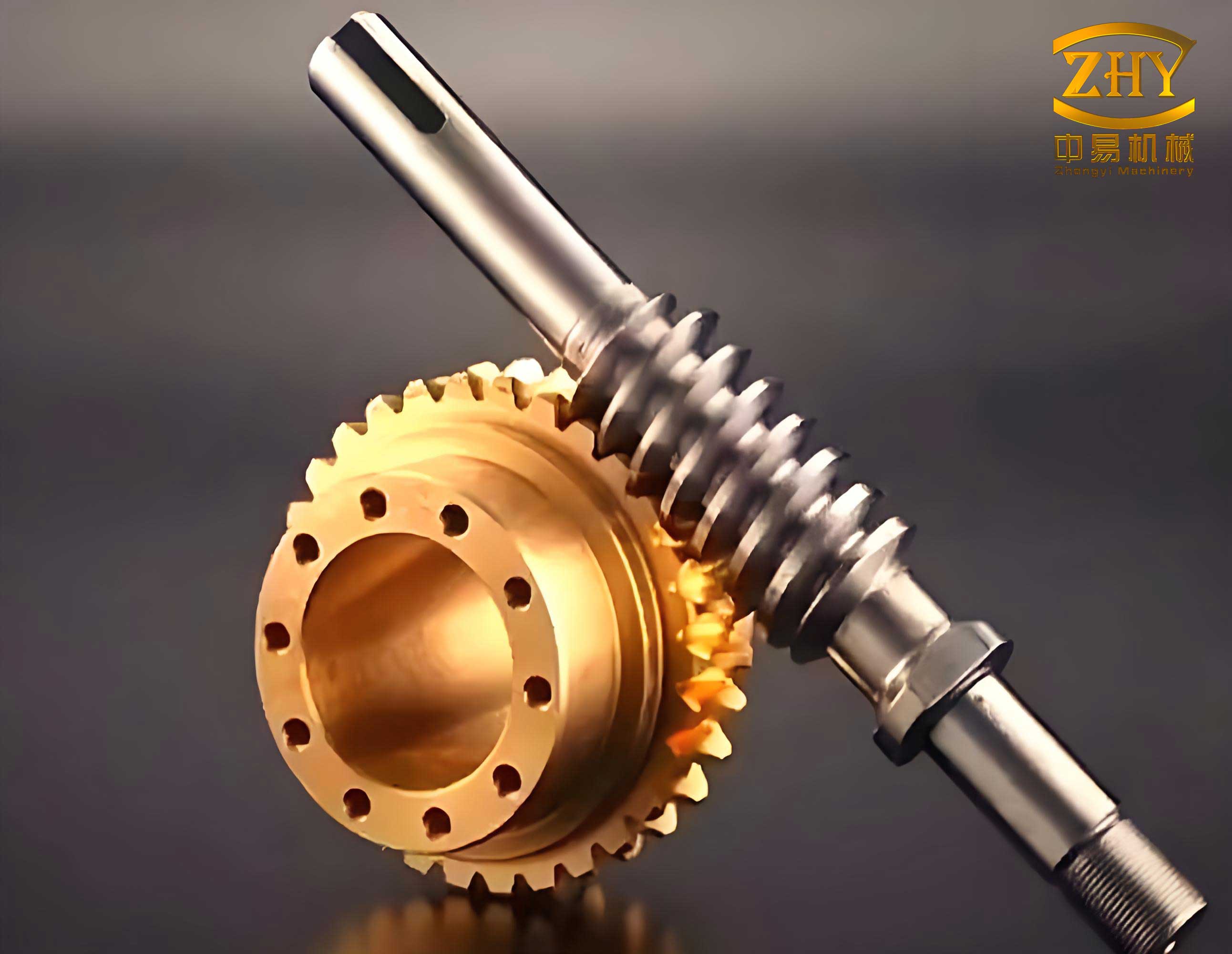
The conventional design procedure for screw gears is a sequential, iterative process guided by established standards and empirical data. It begins with the definition of input conditions: input power ($P_1$), worm rotational speed ($n_1$), desired gear ratio ($i$), operating environment (open/closed), load characteristics, and required service life. Material selection for the worm and the gear wheel is crucial; typically, a hardened steel (e.g., 35CrMo) is used for the worm, while the gear ring is made from a softer, wear-resistant material like bronze (e.g., ZCuSn10P1) to mitigate adhesive wear. The core design steps involve selecting primary parameters such as the number of worm threads ($z_1$), the module ($m$), and the diameter factor ($q$), which defines the worm’s slenderness. Key calculations include determining the center distance ($a$), verifying contact ($\sigma_H$) and bending ($\sigma_F$) stresses against material endurance limits with appropriate safety factors ($S_{Hmin}$, $S_{Fmin}$), and checking the worm shaft for excessive deflection under load to ensure proper meshing. To expedite this process, a dedicated graphical user interface (GUI) module was developed using MATLAB’s GUIDE toolbox. This module encapsulates the design algorithms, material property databases, and interpolation logic for coefficients, allowing for rapid input of conditions and retrieval of a viable, standard-conforming design for the screw gears.
For instance, consider a design task for a set of screw gears with the following specifications: input power $P_1 = 55 \text{ kW}$, worm speed $n_1 = 1000 \text{ rpm}$, gear ratio $i = 10$, operating in a closed housing under relatively steady loads for $L_h = 10,000$ hours. Using the developed GUI, a conventional design was obtained, yielding the key parameters summarized in Table 1.
| Parameter | Symbol | Value | Unit |
|---|---|---|---|
| Center Distance | $a$ | 250 | mm |
| Module | $m$ | 12.5 | mm |
| Number of Worm Threads | $z_1$ | 3 | – |
| Number of Gear Teeth | $z_2 = i \cdot z_1$ | 31 | – |
| Diameter Factor | $q$ | 8.4 | – |
| Worm Pitch Diameter | $d_1 = m \cdot q$ | 105 | mm |
While this design meets all functional requirements, it presents an opportunity for optimization to reduce material consumption, minimize space envelope, and potentially improve performance. The optimization of screw gears is formulated as a constrained nonlinear programming problem.
Formulation of the Optimization Problem for Screw Gears
The optimization seeks to find the best combination of key design variables that minimize one or more objective functions while satisfying all design constraints. For screw gears, the primary design variables are naturally selected as:
$$ \mathbf{x} = [x_1, x_2, x_3]^T = [m, z_1, q]^T $$
where $m$ is the module, $z_1$ is the number of worm threads, and $q$ is the diameter quotient.
Objective Functions
Multiple objectives are considered to address different aspects of screw gear design economy and performance:
- Minimize Center Distance ($f_1$): A smaller center distance leads to a more compact gearbox.
$$ \min f_1(\mathbf{x}) = a = \frac{1}{2}(d_1 + d_2) = \frac{m}{2}(q + i \cdot z_1) $$ - Minimize Approximate Total Volume ($f_2$): This estimates the material volume of the main worm and gear bodies, proportional to cost. The worm length ($b_1$) and gear face width ($b_2$) are approximated by standard formulas.
$$ b_1 \approx (12.5 + 0.09 z_2) \cdot m $$
$$ b_2 \approx 0.45 (d_1 + 6m) $$
$$ \min f_2(\mathbf{x}) = V_{total} \approx \frac{\pi}{4}d_1^2 b_1 + \frac{\pi}{4}d_2^2 b_2 $$ - Minimize Gear Ring Volume ($f_3$): The gear ring, often made of expensive bronze, is a primary cost driver. Minimizing its volume is crucial for economic optimization of screw gears.
$$ d_{a2} = d_2 + 2m \quad \text{(Gear tip diameter)} $$
$$ d_{ring,inner} \approx d_2 – 6.4m $$
$$ \min f_3(\mathbf{x}) = V_{ring} \approx \frac{\pi}{4} (d_{a2}^2 – d_{ring,inner}^2) b_2 $$
To handle this multi-objective problem efficiently, a scalarization technique using a weighted sum is employed, resulting in a single aggregate objective function (AOF):
$$ \min F(\mathbf{x}) = \omega_1 f_1(\mathbf{x}) + \omega_2 f_2(\mathbf{x}) + \omega_3 f_3(\mathbf{x}) $$
Based on priority (with emphasis on saving costly bronze), the weights are chosen as $\omega_1 = 0.25$, $\omega_2 = 0.25$, and $\omega_3 = 0.50$.
Constraint Conditions
The optimization must respect two categories of constraints: boundary limits and performance criteria.
1. Boundary Constraints: These define the feasible range for the design variables based on practical and standard considerations for screw gears.
$$
\begin{aligned}
&g_1(\mathbf{x}) = m_{min} – x_1 \le 0 \quad & \text{(e.g., } m_{min}=6.5 \text{)} \\
&g_2(\mathbf{x}) = x_1 – m_{max} \le 0 \quad & \text{(e.g., } m_{max}=16.0 \text{)} \\
&g_3(\mathbf{x}) = z_{1,min} – x_2 \le 0 \quad & \text{(e.g., } z_{1,min}=2 \text{)} \\
&g_4(\mathbf{x}) = x_2 – z_{1,max} \le 0 \quad & \text{(e.g., } z_{1,max}=6 \text{)} \\
&g_5(\mathbf{x}) = q_{min} – x_3 \le 0 \quad & \text{(e.g., } q_{min}=6.0 \text{)} \\
&g_6(\mathbf{x}) = x_3 – q_{max} \le 0 \quad & \text{(e.g., } q_{max}=14.0 \text{)}
\end{aligned}
$$
2. Performance Constraints: These ensure the optimized screw gears meet strength, efficiency, and rigidity requirements.
- Efficiency Constraint ($g_7$): The total efficiency ($\eta$) must exceed a minimum allowable value (e.g., 0.85). Efficiency depends on the lead angle ($\gamma$) and an equivalent coefficient of friction ($f_v$).
$$ \eta = \eta_{chassis} \cdot \eta_{mesh} \cdot \eta_{bearing} \approx 0.97 \cdot \frac{\tan \gamma}{\tan(\gamma + \rho_v)} \cdot 0.98 $$
$$ \tan \gamma = \frac{z_1}{q} = \frac{x_2}{x_3}, \quad \tan \rho_v \approx f_v $$
The coefficient $f_v$ is a function of sliding velocity $v_s = \frac{\pi d_1 n_1}{60000 \cos \gamma}$, often modeled by an empirical fit: $f_v \approx 0.046 / v_s^{0.4503}$.
Thus, the constraint is:
$$ g_7(\mathbf{x}) = \eta_{min} – \eta \le 0 $$ - Contact Stress Constraint ($g_8$): The calculated contact stress must be below the allowable limit with a defined safety factor.
$$ \sigma_H = Z_E \sqrt{\frac{9.5 K_A T_2}{d_1 d_2^2}} \le \frac{\sigma_{H,\lim}}{S_{Hmin}} $$
$$ g_8(\mathbf{x}) = \sigma_H – \frac{\sigma_{H,\lim}}{S_{Hmin}} \le 0 $$
where $Z_E$ is the elasticity factor, $K_A$ is the application factor, and $T_2$ is the output torque on the gear. - Bending Stress Constraint ($g_9$): The root bending stress in the gear teeth must be within safe limits.
$$ \sigma_F = \frac{1.53 K_A T_2}{d_1 d_2 m} Y_{Fa} Y_\epsilon \le \frac{\sigma_{F,\lim}}{S_{Fmin}} $$
$$ g_9(\mathbf{x}) = \sigma_F – \frac{\sigma_{F,\lim}}{S_{Fmin}} \le 0 $$
where $Y_{Fa}$ and $Y_\epsilon$ are the form factor and contact ratio factor, respectively. - Worm Shaft Deflection Constraint ($g_{10}$): Excessive worm deflection can cause poor tooth contact. The radial deflection ($y$) at the worm’s midpoint must be less than a permissible value (e.g., $[y] = 0.001 \sqrt{m}$ [mm]).
$$ y = \frac{\sqrt{F_{t1}^2 + F_{r1}^2}}{48 E I} L^3 \le [y] $$
$$ g_{10}(\mathbf{x}) = y – [y] \le 0 $$
Here, $F_{t1}$ and $F_{r1}$ are the tangential and radial forces on the worm, $E$ is Young’s modulus, $I$ is the moment of inertia of the worm’s root diameter, and $L$ is the bearing span.
Solution and Comparative Analysis
The formulated optimization problem for the screw gears was solved using MATLAB’s fmincon solver, which is suited for constrained nonlinear minimization. For verification and exploration of the global optimum, a Particle Swarm Optimization (PSO) algorithm was also implemented. Both methods converged to similar optimal points in the design space, as shown in Table 2. The continuous variable results from the solvers were then rounded to standard/preferred values for practical manufacturing (m=10, z1=4, q=9). The final optimized design was re-evaluated to ensure all constraints were satisfied, which they were.
| Design Approach | Module, $m$ (mm) | Worm Threads, $z_1$ | Diam. Factor, $q$ | Center Dist., $a$ (mm) | Total Vol., $V_{total}$ (mm³) | Gear Ring Vol., $V_{ring}$ (mm³) |
|---|---|---|---|---|---|---|
| Conventional | 12.5 | 3 | 8.4 | 250.0 | 1.1121 × 10⁷ | 5.4754 × 10⁶ |
| fmincon Solution | 10.1573 | 3.8239 | 8.5886 | 237.8 | 8.8730 × 10⁶ | 3.7116 × 10⁶ |
| PSO Solution | 10.2177 | 3.7891 | 8.5389 | 237.2 | 8.8440 × 10⁶ | 3.7295 × 10⁶ |
| Final Optimized* | 10.0 | 4 | 9.0 | 245.0 | 9.5528 × 10⁶ | 3.8172 × 10⁶ |
*Rounded values, requires a slight positive profile shift ($x_b=+0.5$) to maintain the nominal center distance of ~250 mm if needed.
The results demonstrate a significant improvement achieved through the optimization of these screw gears. Although the center distance reduction is modest (from 250 mm to a calculated 245 mm), the volumetric savings are substantial. The approximate total volume is reduced by approximately 14.1%, and, more importantly, the volume of the expensive bronze gear ring is reduced by about 30.3%. This translates directly into lower material costs and lighter weight for the screw gear set while maintaining all performance standards for strength, efficiency, and rigidity.
Extended Discussion on Screw Gear Optimization Factors
The successful optimization of screw gears hinges on the accurate modeling of several complex, interdependent phenomena. Beyond the basic model presented, further refinements can be incorporated for higher-fidelity analysis.
Thermal Constraints: For power-dense screw gear drives, heat generation and dissipation become critical. An additional thermal constraint can be formulated to ensure the equilibrium oil temperature does not exceed limits. The heat generated ($Q_{gen}$) is primarily due to power loss from mesh friction and churning, while heat dissipated ($Q_{diss}$) depends on the housing surface area and cooling conditions.
$$ Q_{gen} = P_{in} (1 – \eta) $$
$$ Q_{diss} = k_s A (T_{oil} – T_{ambient}) $$
A thermal constraint would enforce:
$$ g_{11}(\mathbf{x}) = T_{oil,calc} – T_{oil,max} \le 0 $$
This constraint often pushes the design towards screw gears with higher inherent efficiency (e.g., by favoring a higher number of worm threads $z_1$ or a larger lead angle $\gamma$).
Dynamic and Wear Considerations: For screw gears operating under variable loads or high speeds, dynamic load factors may need to be integrated into the stress calculations. Furthermore, a wear constraint based on the calculated sliding velocity and specific lubricant film thickness could be added to ensure long-term reliability of the screw gears, preventing premature failure due to scuffing or excessive wear.
Sensitivity Analysis: After obtaining an optimal point, it is instructive to perform a sensitivity analysis on the screw gear design. This involves perturbing the optimal design variables and key input parameters (like input torque or required life) to observe the change in the objective function and active constraints. Mathematically, this explores the local behavior of the optimization landscape.
$$ S_{v} = \frac{\partial F^*}{\partial v} $$
where $v$ is a parameter (e.g., input power $P_1$) and $F^*$ is the optimal objective value. This analysis reveals which parameters the screw gear design is most sensitive to, guiding manufacturing tolerances and highlighting potential risks if operating conditions deviate from the design point.
Advanced Optimization Algorithms: While gradient-based methods like fmincon and population-based methods like PSO were used successfully, other algorithms can be explored for the optimization of screw gears. Genetic Algorithms (GAs) are robust for global search, especially with discrete/standardized variable values. Sequential Quadratic Programming (SQP) can be very efficient for local refinement. A hybrid approach, using a global method (PSO/GA) to locate a promising region and a local gradient method to fine-tune the solution, often yields the best results for complex mechanical systems like screw gears.
Conclusion
This detailed exploration presents a robust framework for the design and optimization of screw gears, specifically the arc-contact cylindrical type. The methodology begins with an efficient conventional design process automated through a custom MATLAB GUI, ensuring a compliant baseline design. It then advances to a formal optimization paradigm, where key geometric parameters—module, number of worm threads, and diameter factor—are treated as design variables. The multi-objective problem, aiming to minimize center distance, total volume, and critically, the volume of the costly gear ring, is scalarized into a single objective function. A comprehensive set of boundary and performance constraints, encompassing efficiency, contact and bending strength, and shaft rigidity, defines the feasible design space for the screw gears.
The application of numerical optimization solvers, corroborated by a metaheuristic algorithm, yielded a significantly improved design. The optimized screw gears demonstrate a marked reduction in material usage, particularly for the bronze gear ring, leading to direct economic benefits and potential weight savings, while rigorously satisfying all operational requirements. This integrated approach, combining systematic design principles with advanced computational optimization techniques, provides a powerful and practical tool for engineers to develop high-performance, cost-effective screw gear drives for a wide range of mechanical transmission applications.