
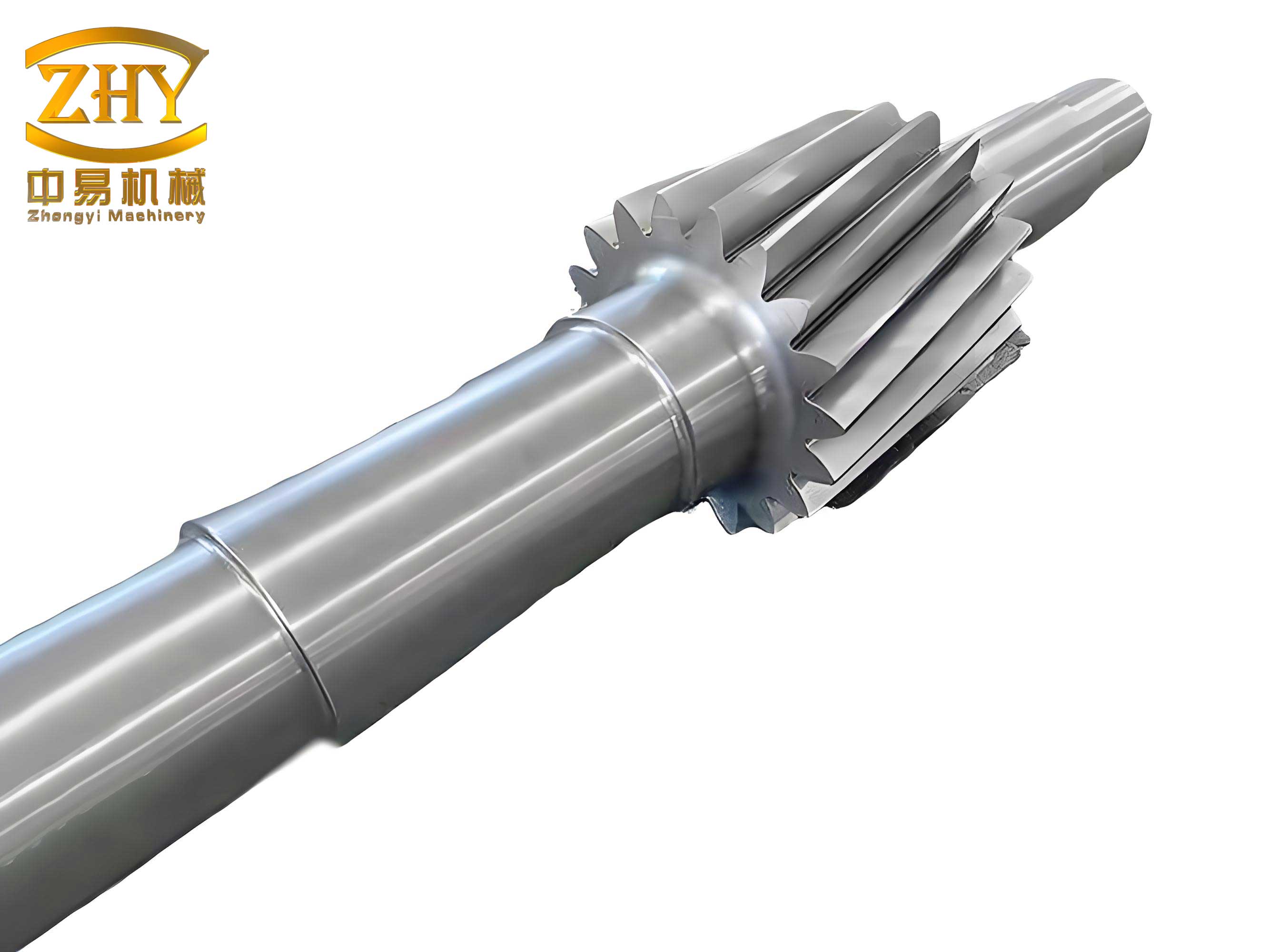
The manufacturing of automotive gear shafts is a precision-driven process where the final grinding operation is critical for achieving the necessary tolerances, surface finish, and geometric accuracy essential for power transmission performance and durability. Historically, this stage has been heavily reliant on manual labor for tasks such as loading raw blanks, unloading finished parts, and most critically, the precise rotational alignment or “phasing” of the gear teeth relative to the grinding wheel—a process known as indexing or “tooth alignment.” This manual dependence introduces significant challenges: high labor intensity, inconsistent working conditions, variable production rates, and a substantial risk of part damage during handling. Furthermore, the industry faces growing difficulties in attracting and retaining skilled operators for such demanding roles, leading to increased management complexity and instability in production output and quality.
While modern CNC grinders equipped with linear axes and automatic loading mechanisms exist, they often come with a high capital cost and limited flexibility. Many still require manual intervention for initial setup or complex parts handling, failing to deliver a fully autonomous and adaptable solution. This gap highlights the relatively low penetration of comprehensive automation in gear shaft finishing. This article, from the perspective of a system designer, explores the advantages of industrial robotics in this domain and details the conception and implementation of a flexible, automated grinding cell centered around a robotic manipulator. The core objective is to replace human effort in the material handling and setup phases, thereby enhancing consistency, throughput, and overall equipment effectiveness (OEE) for gear shaft production.
The Imperative for Automated Material Handling
In a typical production scenario, an operator manages multiple CNC grinders, performing repetitive and physically demanding tasks. The manual transfer of heavy or delicate gear shafts between pallets, fixtures, and machines is a primary source of variability. Inconsistencies in placement force, alignment speed, and handling care directly impact scrap rates and non-conformance. The economic pressure is twofold: rising labor costs and scarcity on one side, and intensifying market competition demanding higher quality and lower prices on the other. Automation presents a compelling solution. An industrial robot offers unmatched consistency, repeatability, and endurance. Every gear shaft is picked, placed, and positioned with identical precision, cycle after cycle, for 24 hours a day. This capability not only safeguards product quality by eliminating handling damage but also provides a predictable, high-volume output that is essential for modern manufacturing planning and supply chain reliability. The programmable nature of robots also introduces valuable flexibility, allowing the same cell to be reconfigured for different gear shaft families with minimal downtime, compared to dedicated hard automation. Therefore, the design focus shifts to creating a robotic system that can reliably service one or more grinding machines, performing all loading, unloading, and pre-set alignment operations.
| Aspect | Manual Operation | Robotic Automation |
|---|---|---|
| Labor Intensity | High (lifting, precise alignment) | Minimal (human supervises) |
| Consistency | Variable (operator-dependent) | Extremely High (program-defined) |
| Uptime | Limited by shifts/breaks | Near 24/7 (with maintenance) |
| Part Handling Damage | Higher Risk | Very Low Risk |
| Production Flexibility | Low (skill-based) | High (reprogrammable) |
| Long-Term Cost | Increasing (wages, turnover) | Predictable (capital & maintenance) |
Overall System Architecture and Design Philosophy
The proposed automated grinding system is an integrated cell where synergy between components is paramount. The core components include: one or more CNC grinding machines, an industrial robot, a dedicated part feeding system (like a conveyor or magazine), a centralized Programmable Logic Controller (PLC), and safety peripherals. The PLC acts as the cell’s nervous system, orchestrating communication and synchronization between all equipment. The robot is the primary material handler. The design philosophy prioritizes robustness, simplicity of operation, and maximizing the utilization of the grinding process itself, which is the value-adding operation. The system’s advantages are multifaceted:
- It rationalizes the entire workflow for gear shaft grinding, from raw blank to finished part, under unified automated control.
- It integrates feeding, precise locating, clamping, and transfer functions into a seamless sequence.
- It employs a custom-designed robotic end-effector capable of continuous, reliable operation.
- It interfaces with modified or standard grinding machine fixtures to enable automated part clamping and release.
- It utilizes advanced, yet user-friendly, robot programming for intuitive control, state monitoring, and diagnostics.
The overall goal is to create a “lights-out” capable manufacturing island for gear shaft finishing, where human intervention is only required for system startup, bulk loading/unloading, and maintenance.
Industrial Robot Selection and Rationale
The selection of the industrial robot is critical. Key parameters include payload capacity, reach, degrees of freedom (DOF), repeatability, and the suitability of its controller for integration. For handling typical automotive gear shaft components, the payload requirement is often moderate (e.g., under 10 kg), but the need for dexterity is high. The robot must reach into a grinding machine’s work envelope, precisely place a gear shaft into a fixture, and possibly perform a rotational alignment maneuver. A six-axis articulated robot is ideal, offering the necessary flexibility to approach from optimal angles and orient the part correctly.
For this system design, a robot like the Stäubli TX90 is an excellent candidate. Its compact design, high precision, and powerful VAL3 programming environment make it suitable for intricate tasks. The VAL3 language, with its structured, procedural syntax similar to C, allows for creating complex, modular programs for path planning, error handling, and external communication. The robot’s specifications should meet or exceed the following core requirements:
| Parameter | Target Specification | Rationale |
|---|---|---|
| Number of Axes | 6 | Full spatial flexibility for part orientation and machine access. |
| Max. Payload | >7 kg | Must safely handle the weight of the heaviest gear shaft variant plus end-effector. |
| Reach (Radius) | >950 mm | Must cover distance between part source, grinders, and finished part drop-off. |
| Repeatability | ±0.02 mm or better | Critical for precise insertion into grinding fixture and consistent positioning. |
| Controller | Open for PLC I/O & Fieldbus | Essential for seamless integration into the larger cell control system. |
The positional repeatability, often denoted as $$ RP = \pm \delta $$ where $\delta$ is the statistical variation in position, is a key performance metric. For a gear shaft, consistent placement within the fixture is vital to ensure grinding wheel engagement is correct for every part, directly influencing tooth profile accuracy.
Cell Layout and System Configuration
An efficient physical layout minimizes robot motion waste and maximizes floor space utilization. A common configuration is a robot-centric cell. For servicing two grinders, the robot is positioned centrally. Grinder A and Grinder B are placed opposing each other, with the robot’s reach envelope encompassing both work zones. A part feeding system, such as a rotary table with pallets or a linear conveyor with pedestal fixtures, is located within easy reach. A finished parts rack or conveyor is positioned on the opposite side or adjacent to the feeding system. This layout allows the robot to perform a continuous, optimized cycle: pick raw gear shaft from feeder, load into Grinder A, move to pick next part, load into Grinder B, then unload finished parts from both machines and deposit them. The cycle time $T_{cycle}$ is governed by the longest parallel process, ideally the grinding time $T_{grind}$, and can be estimated as:
$$ T_{cycle} \approx \max(T_{grind}, T_{robot\_handling}) + T_{safety\_margin} $$
where $T_{robot\_handling}$ is the time for all pick-and-place motions. The goal is to have $T_{robot\_handling} < T_{grind}$ so the robot does not become the bottleneck.
Electrical Control System Integration
The PLC is the master controller of the cell. It does not directly control the robot’s intricate movements (that is the robot controller’s role) but manages the overall sequence, interlocking, and safety. The control system architecture follows a hierarchical model. The PLC communicates with:
- Robot Controller: Sends commands like “Cycle Start,” “Load Part,” “Unload Part,” and receives status signals like “Busy,” “Error,” “Ready.”
- CNC Grinders: Monitors machine states (“Idle,” “Running,” “Door Open,” “Alarm”), triggers the start of the grinding cycle, and receives “Cycle Complete” signals.
- Feeding System: Commands the advancement of pallets or conveyors and verifies part presence via sensors.
- Safety System: Monitors safety gates, light curtains, and emergency stops, disabling all motion when triggered.
- Human-Machine Interface (HMI): Provides operators with system status, production counts, alarm messages, and manual control buttons.
This integrated network ensures that the robot only moves to load a grinder when its door is open and it is in a ready state. Similarly, the grinder only starts its cycle after receiving confirmation that the robot has cleared the work area and the door is closed. This level of handshaking is crucial for safety and process reliability.
Detailed Workflow and Cycle Analysis
The operational workflow is a precisely choreographed sequence. Assume a cell with one robot, one feeding station, and two grinders (A and B).
- Initialization: The feeding station presents a raw gear shaft at the pick-up position. Grinders A and B are idle, doors open, fixtures empty.
- Cycle Start: The PLC, seeing all conditions met, sends a start signal to the robot.
- Step 1 – Pick from Feeder: Robot moves to the feeder, grips the raw gear shaft with its end-effector.
- Step 2 – Load Grinder A: Robot moves to Grinder A, inserts the gear shaft into the fixture, activates the fixture clamp (via pneumatic signal or robot tool), retracts, and signals “Part Loaded.”
- Step 3 – Command Grinder A: PLC commands Grinder A to close door and start its grinding program.
- Step 4 – Pick Next Part: Robot returns to feeder, picks the next raw gear shaft.
- Step 5 – Load Grinder B: Robot loads Grinder B, similar to Step 2. PLC starts Grinder B.
- Step 6 – Unload & Swap (Grinder A): Robot waits (or performs idle moves) until Grinder A signals completion. Robot then unloads the finished gear shaft from Grinder A, places it directly onto the finished parts conveyor, picks a new raw part from the feeder, and loads it back into Grinder A, restarting its cycle. This “unload-then-load” sequence is efficient.
- Step 7 – Unload & Swap (Grinder B): The same sequence as Step 6 is performed for Grinder B when it completes.
The system state can be modeled. Let $S_{G}$ represent the state of a Grinder (0=Idle/Ready, 1=Running, 2=Finished). Let $S_{R}$ represent the Robot state (0=Idle, 1=Moving to Pick, 2=Holding Part, 3=Loading, 4=Unloading). The PLC’s logic continuously evaluates a state matrix to decide the next action. The throughput $Q$ of the cell, in parts per hour, can be approximated by:
$$ Q \approx \frac{3600}{T_{cycle}} \times N_{active\_grinders} $$
where $N_{active\_grinders}$ is 2 in this case, assuming the robot keeps both machines busy.
| Step | Robot Action | Grinder A State | Grinder B State | Feeder State | PLC Command |
|---|---|---|---|---|---|
| 1 | Pick Raw Part | Idle, Door Open | Idle, Door Open | Part Presented | Robot Start |
| 2 | Load Grinder A | -> Loading | Idle | Empty | – |
| 3 | – | -> Running | Idle | Advance | Start Grind A |
| 4 | Pick Raw Part | Running | Idle | Part Presented | – |
| 5 | Load Grinder B | Running | -> Running | Empty | Start Grind B |
| 6 | Unload A, Load A | Finished -> Running | Running | Part Presented | Restart Grind A |
End-Effector Design and Gripper Technology
The robot’s end-effector, or tool, is custom-designed for the specific gear shaft geometry. The primary function is to securely grip the part without causing damage to machined surfaces, especially the gear teeth or bearing journals. For cylindrical shafts, a two or three-jaw gripper is typically used. The choice between angular and parallel motion jaws depends on the part’s shape; parallel grippers are often preferred for cylindrical gripping as they apply a centering force.
In a sophisticated design, a dual-gripper end-effector can be employed to dramatically reduce cycle time. This tool features two independent grippers on a single mounting plate. One gripper holds a raw gear shaft, while the other is positioned to pick up a finished part. In one combined motion into the machine, the robot can unload the finished part with Gripper #2 and immediately load the raw part with Gripper #1, then retract. This eliminates two separate robot in/out movements per machine. The gripping force $F_g$ required must overcome the weight and any acceleration forces:
$$ F_g \geq m \cdot (g + a_{max}) \cdot \mu^{-1} $$
where $m$ is the mass of the gear shaft, $g$ is gravity, $a_{max}$ is the maximum robot acceleration during transport, and $\mu$ is the coefficient of friction between the gripper jaws and the part surface. A safety factor (e.g., 2) is always applied.
Actuation is commonly pneumatic due to its simplicity, speed, and low cost. A double-acting cylinder drives the jaw motion. Magnetic sensors integrated into the cylinder body provide feedback to the robot controller on whether the gripper is “Open” or “Closed,” a critical signal for process reliability. For handling fragile gear teeth, custom soft or shaped jaw inserts made from polyurethane or aluminum with protective coatings are used to distribute the gripping force over a larger area.
System Performance and Advantages
The implementation of such a robotic grinding cell delivers transformative benefits. From an operational standpoint, the system exhibits high reliability and consistent cycle times, leading to a significant increase in equipment utilization and overall productivity. The automated handling virtually eliminates gear shaft damage caused by manual dropping or misalignment, directly improving first-pass yield rates. The stable, predictable output facilitates just-in-time production and improves responsiveness to demand fluctuations.
Economically, the system mitigates the risks associated with labor shortages and rising wages. While the initial capital investment is substantial, the return on investment (ROI) is realized through higher throughput, superior quality (reducing scrap and rework costs), and the ability to operate unattended for extended periods. The flexibility of the robot allows the same cell to be adapted for new gear shaft designs with primarily program changes and minor tooling adjustments, protecting the investment against product lifecycle changes.
Technically, the integration of precise robotic handling with advanced CNC grinding creates a synergistic effect. The grinding process parameters can be optimized with the confidence that every gear shaft is presented to the wheel in an identical position and orientation. This consistency allows for pushing the process towards its limits for efficiency while maintaining quality, something difficult to achieve with manual intervention. The data logging capabilities of modern PLCs and robot controllers also enable detailed production analytics and traceability for each gear shaft batch.
Conclusion and Future Directions
The design and deployment of an industrial robot-based automation system for automotive gear shaft grinding address the core challenges of modern manufacturing: quality, efficiency, and flexibility. By taking over the repetitive, precise, and physically demanding tasks of part handling and pre-set alignment, the robotic cell unlocks the full potential of CNC grinding technology. The system described herein—centered on a precise 6-axis robot, integrated via a master PLC, and equipped with a purpose-designed end-effector—provides a robust blueprint for achieving high-volume, high-precision finishing of gear shaft components.
The future evolution of such systems points towards even greater intelligence and autonomy. Integration with machine vision could allow the robot to visually identify and locate randomly placed gear shaft blanks in a bin, enabling true flexible feeding. In-process gauging feedback could be incorporated, where a measurement probe on the robot or the grinder itself checks critical dimensions post-grind and feeds data back to adjust grinding parameters adaptively for the next part, closing the quality control loop. Furthermore, advancements in collaborative robot (cobot) technology may simplify deployment and allow for safer, closer human-robot interaction in setup and maintenance tasks. The journey towards fully autonomous, intelligent manufacturing for critical components like the automotive gear shaft is well underway, with robotic automation serving as its foundational pillar.