1. Introduction
Gears play a crucial role in mechanical 传动 systems, facilitating the transfer of power and motion with high efficiency and precision. Among various types of gears, arc cylindrical gears have unique characteristics that make them suitable for specific applications. This article delves into the design, manufacture, and application of arc cylindrical gears, aiming to provide a comprehensive understanding of this important component in mechanical engineering.
Arc cylindrical gears, with their distinct tooth shape and structure, offer several advantages over traditional gear types such as straight and helical gears. Their tooth profile is designed in a way that enhances load – carrying capacity, reduces noise and vibration during operation, and improves the overall smoothness of power transmission. These gears are particularly useful in heavy – duty machinery, automotive transmissions, and other applications where high – torque and reliable operation are required.
However, the design and manufacture of arc cylindrical gears are more complex compared to common gears. Specialized knowledge and techniques are needed to ensure that these gears meet the required performance standards. In the following sections, we will explore the fundamental aspects of arc cylindrical gears, including their basic parameters, design principles, manufacturing methods, and practical applications.
2. Basic Parameters and Design Principles of Arc Cylindrical Gears
2.1 Basic Parameters
The design of arc cylindrical gears begins with an understanding of their basic parameters. These parameters are fundamental to defining the size, shape, and performance characteristics of the gears. The main basic parameters of arc cylindrical gears are presented in Table 1.
| Parameter | Symbol | Explanation |
|---|---|---|
| Modulus | Determines the size of the gear teeth. It is calculated based on the strength requirements of the gear and is a key factor in gear design. A larger modulus generally indicates larger teeth and higher load – carrying capacity. | |
| Number of Teeth | The number of teeth on the gear affects the gear ratio and the overall performance of the gear system. When designing a gear pair, the number of teeth on the small gear () and the large gear () are chosen based on the required gear ratio (), where . Special consideration is given to the minimum number of teeth () to avoid root – cutting in the design of the small gear. | |
| Pressure Angle | The pressure angle is an important parameter that affects the force transmission and meshing characteristics of the gears. In arc cylindrical gears, the pressure angle in the central section is typically set to , which is a common value that provides a good balance between load – carrying capacity and smooth meshing. | |
| Addendum Coefficient | This coefficient determines the height of the gear tooth above the pitch circle. A standard value of is usually used, which is based on industry – wide practices and provides suitable tooth profiles for most applications. | |
| Clearance Coefficient | The clearance coefficient defines the space between the teeth of two meshing gears. A value of is commonly adopted to ensure proper lubrication and to prevent interference between the teeth during meshing. |
2.2 Design Principles
The design of arc cylindrical gears follows similar principles to those of involute spur gears in many aspects. The main design criteria are centered around ensuring the gear’s ability to withstand the expected loads without failure. The two primary failure modes considered in gear design are tooth – surface fatigue pitting and tooth – root fatigue fracture.
Based on the application scenario of the gear transmission, designers can choose either the tooth – surface contact fatigue strength or the tooth – root bending fatigue strength design calculation criterion. For example, in applications where smooth operation and low noise are crucial, such as in precision machinery, the tooth – surface contact fatigue strength may be the primary consideration. In contrast, for heavy – duty applications like mining equipment, the tooth – root bending fatigue strength is often more critical.
The design process typically starts with the selection of gear materials, heat – treatment methods, and accuracy grades. The choice of materials depends on factors such as the expected load, operating environment, and cost. Heat – treatment is used to enhance the mechanical properties of the gear material, improving its hardness, strength, and wear resistance. The accuracy grade of the gear affects its meshing performance, noise level, and overall efficiency.
After determining these factors, the design calculation is carried out to determine the number of teeth and modulus of the small gear. Once the small gear parameters are set, the large gear parameters can be calculated based on the gear ratio. Finally, the main dimensions of the arc cylindrical gears are calculated using the geometric dimension formulas, and the gear strength is checked to ensure that it meets the design requirements. The geometric dimension calculation formulas for arc cylindrical gears are shown in Table 2.
3. Manufacturing Methods of Arc Cylindrical Gears
3.1 Cutting Methods
The manufacturing of arc cylindrical gears involves several processes, with the cutting process being a crucial step. Currently, the more typical cutting methods for arc cylindrical gears are the rotating cutter head method and the parallel link method. Among these, the rotating cutter head method is widely used due to its high efficiency and ease of implementation.
The principle of the rotating cutter head method is that during the cutting process, there is an accurate generating motion relationship between the cutting cutter head and the gear blank. Specifically, the linear velocity of the pitch circle of the gear blank being processed is equal to the linear velocity of the pitch line of the cutting cutter head. In addition to the main rotating motion, the cutting cutter head also has a radial feeding motion towards the gear blank during the gear tooth cutting process.
When using the generating method for processing, only one tooth space can be cut at a time. After cutting each tooth space, the gear blank needs to be accurately indexed before cutting the next tooth space until all tooth spaces are cut. Although it is theoretically possible to use a double – edged cutter to cut a complete tooth space at once, forming the convex and concave surfaces of the gear tooth, in practice, this method has limitations. The double – edged cutter experiences high cutting forces and rapid tool wear during full – edge cutting, resulting in low – precision tooth surfaces.
To overcome these problems, a single – edged cutter cutting method has been proposed. In this method, the gear tooth groove is first roughed out using a double – edged cutter, and then the convex and concave surfaces of the arc cylindrical gear are separately finished using single – edged cutters. This approach can improve the tooth surface accuracy. Additionally, the single – edged double – milling method has been developed. In this method, a special milling machine is equipped with two workstations to separately cut the convex and concave surfaces of the gear teeth, which further improves the processing efficiency and precision while addressing the issues of tool change and gear blank installation.
3.2 Tooth Surface Equation of the Cutting Tool
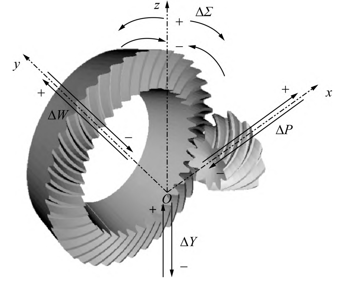
To design and manufacture specialized cutting tools for arc cylindrical gears, it is necessary to establish the tooth surface equation of the cutting tool based on the cutting principle of the rotating cutter head method. By establishing relevant coordinate systems, including the coordinate system fixed on the gear blank, the coordinate system fixed on the milling cutter head, and the fixed coordinate system, the tooth surface parameter equation of the cutting tool can be derived.
The tooth surface parameter equation of the cutting tool is expressed as:
where is the distance from a point on the tool surface along the conical surface bus to the reference point, is the rotation angle of the tool holder from the central section of the gear blank to the end face, and is the tool pressure angle. This equation is essential for accurately manufacturing the cutting tool and ensuring the precision of the gear teeth.
3.3 Cutting Process and Macro – Program Compilation
The cutting process of arc cylindrical gears can be divided into three steps. First, a three – edged tooth – groove milling cutter is used to mill the tooth groove in the middle of the arc cylindrical gear tooth groove, removing most of the gear blank material. Then, single – edged cutters are used in the second and third steps to process the concave and convex tooth surfaces of the arc cylindrical gear respectively.
When processing on a special milling machine, the indexing of the processing process can be programmed using both absolute indexing and relative indexing methods. For example, if the indexing angle of the gear according to the number of teeth is , the machining program starts from in the first step, which is to rough – machine the tooth groove from the middle of the gear tooth groove. In the second step, the cutter starts from , and in the third step, it starts from , using two single – edged cutters to process the corresponding concave and convex tooth surfaces.
[Insert an image here showing the three – step cutting process of arc cylindrical gears]
Since the cutter enters along the involute profile, the cutter’s entry trajectory needs to follow the involute curve. A macro – program can be compiled for the cutting cycle of one tooth groove. For example, for an arc cylindrical gear with a modulus , number of teeth , addendum coefficient , and clearance coefficient , the macro – program can be written as shown in the previous research. During the milling process of arc cylindrical gears, the cutter’s entry and exit should be along the involute trajectory, and care must be taken to avoid over – cutting the unprocessed tooth surface to ensure sufficient machining allowance for the tooth surface and guarantee the machining quality.
4. Performance and Application of Arc Cylindrical Gears
4.1 Meshing Performance
The meshing performance of arc cylindrical gears is a key factor in evaluating their quality. After the arc cylindrical gears are manufactured, they need to be tested for meshing transmission. The results of the meshing transmission test of the trial – cut arc cylindrical gears show that these gears have good meshing performance and can meet the expected requirements.
During the meshing process of arc cylindrical gears, each pair of gear teeth engages and disengages gradually. This characteristic is different from that of straight – tooth cylindrical gears, which experience sudden loading and unloading of the load along the entire tooth width during meshing, resulting in large impact and noise. Compared with helical gears, arc cylindrical gears do not have significant axial forces during meshing, which improves the stability of the transmission system.
The good meshing performance of arc cylindrical gears is mainly due to their unique tooth shape and structure. The tooth profile design ensures a large contact area between the meshing teeth, reducing the contact stress and improving the load – carrying capacity. At the same time, the gradual meshing process also helps to reduce vibration and noise, making arc cylindrical gears suitable for applications where high – precision and smooth operation are required.
4.2 Applications
Arc cylindrical gears have a wide range of applications in various fields due to their excellent performance characteristics. In the automotive industry, they are used in transmissions to improve the power – transmission efficiency and reduce noise and vibration during operation. Their ability to withstand high torques and provide smooth power transfer makes them ideal for modern automotive powertrain systems.
In heavy – duty machinery such as mining equipment, construction machinery, and industrial crushers, arc cylindrical gears are also widely used. These machines often operate under harsh conditions with high loads and vibrations. Arc cylindrical gears’ high load – carrying capacity, low axial forces, and good meshing performance enable them to reliably transmit power and ensure the normal operation of the machinery.
In addition, arc cylindrical gears are also used in some precision machinery and instruments. Their high – precision meshing characteristics can meet the requirements for accurate motion transmission in these devices, ensuring the accuracy and stability of the operation.
5. Challenges and Future Developments
5.1 Challenges in Manufacturing
Although arc cylindrical gears have many advantages, their manufacturing process still faces some challenges. One of the main challenges is the need for specialized processing equipment and milling cutters. The high – cost of these specialized tools and equipment limits the large – scale production and application of arc cylindrical gears to a certain extent.
Another challenge is the complexity of the manufacturing process. The precise control of the cutting process, especially the indexing accuracy and the accuracy of the tooth surface machining, requires high – level manufacturing techniques and skilled operators. Any deviation in the manufacturing process may affect the quality and performance of the gears.
5.2 Future Developments
To overcome the current challenges and further promote the development and application of arc cylindrical gears, several future development directions can be considered. Firstly, research and development efforts can be focused on improving the manufacturing process and reducing costs. This can be achieved through the development of new manufacturing technologies and the optimization of existing processes. For example, the use of advanced numerical control techniques and intelligent manufacturing systems can improve the machining accuracy and efficiency while reducing the dependence on skilled labor.
Secondly, the design of arc cylindrical gears can be further optimized. By using advanced computer – aided design (CAD) and finite – element analysis (FEA) methods, designers can better understand the stress distribution and deformation characteristics of the gears under different working conditions, and then optimize the gear design to improve its performance and reliability.
Finally, the application scope of arc cylindrical gears can be expanded. With the continuous development of new technologies and industries, there will be more potential applications for arc cylindrical gears. For example, in the emerging fields of 新能源 and robotics, arc cylindrical gears may find new application opportunities due to their excellent performance characteristics.
6. Conclusion
Arc cylindrical gears are an important type of gear in mechanical engineering, with unique design features, manufacturing methods, and performance advantages. Their good meshing performance, high load – carrying capacity, and low axial forces make them suitable for a wide range of applications in automotive, heavy – duty machinery, and precision equipment.
However, the manufacturing of arc cylindrical gears is complex and requires specialized equipment and techniques. To promote their wider application, it is necessary to continue to improve the manufacturing process, reduce costs, and optimize the design. With the continuous development of technology, arc cylindrical gears are expected to play an even more important role in the future of mechanical engineering, contributing to the development of various industries.