
As the main power source of vehicles, diesel engines play an important role in the development of the national economy.play a very important role. The power transmission of diesel engines includes belt transmission dynamic, gear drive, chain drive, etc. Among them, the gear drive structure is compact and has The gear ratio of the transmission is higher than that of other transmission forms under the same power and transmission ratio conditions. The structure is much more compact. At the same time, it has a wide range of applications and can meet the needs of various machines.With the same requirements, the transmission power range is wide, ensuring a constant transmission ratio, and The mechanical efficiency is high, generally reaching 0.90-0.98.
Gear transmission systems are widely used in diesel engines, especially for cam
Centrally mounted diesel engines have great advantages. In order to better ensure the
Many scholars have improved and optimized the gear system for good operation.
The geometric error of gears is one of the important factors affecting vehicle noise. Liu Shihao
By considering the geometric error of the tooth surface modeling, contact analysis, vibration simulation, acoustic Simulation proposes a method for predicting transmission noise through geometric error.
The influence of gear geometric errors on each link is discussed. Analysis The influence of tooth side clearance on gear knocking noise of a six-cylinder diesel engine The influence of the gear train is analyzed, and the idea of replacing the intermediate transition gear with a shear gear is proposed.
Optimization plan. For the squeal of a diesel engine timing gear phenomenon, and established a timing gear system that considers the flexibility of the timing gear support system A dynamic model analyzes the transmission error, contact patch, and Vibration contribution, a method for controlling the surface quality of gear tooth surface machining is proposed Based on the actual working conditions of the diesel engine crankshaft gear assembly, a tooth profile scheme was obtained. The influence of the interference fit of the wheel assembly on the force of the gear, and through the addition of grooves The comparison of the calculation results of the model provides a method for improving the stress distribution of the gear. As the gear system body The gears are gradually becoming smaller, and people improve the carrying capacity of the gears, thereby reducing the gear system. This study mainly focuses on the design of the gear transmission system for the 4105 diesel engine.It mainly includes crankshaft gears, camshaft gears, idler gears, oil pump gears, etc.The camshaft gear, timing idler gear, and injection pump timing gear are all driven by the crankshaft When the gear is driven. The timing gear of the crankshaft, the timing gear of the fuel injection pump, and the camshaft The transmission ratio of the gears is 2:1. Then mark the position of each gear to install it. Perform calculations to ensure the good operation of the gear system.
Gear system design
The center position of the crankshaft gear, camshaft gear, idler gear and oil pump gear
It has been determined on the engine body.
gear design
crankshaft gear
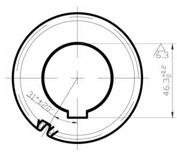
The spiral direction of the crankshaft timing gear size is left-handed. It is mainly made of steel materials. Features: In order to withstand the constantly changing gas pressure and inertia Due to the effects of sexual force and centrifugal force generated during rotation, it is required to have sufficient strength and rigidity, as well as wear resistance and good lubrication.Good, the installation is fixed and reliable, and it is subject to axial positioning or limited axial displacement. In addition, the arrangement of the cranks should be reasonable to meet the requirements of the diesel engine’s firing sequence and stable operation. Function: installed on the front end of the crankshaft to drive the timing idler gear, thereby driving the camshaft gear and fuel injection The pump timing gear ensures the valve timing during engine operation, enabling the opening and closing of the intake and exhaust valves to be consistent with the movement of the piston. Material: 20CrMnTi. After carburizing and quenching, the surface hardness of the crankshaft timing gear can reach 5863 HRC, and the core hardness can reach 32-42 HRC.
camshaft gear
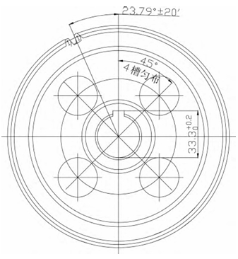
The size of the camshaft gear is shown in the figure, and the spiral direction is left-handed. It is mainly made of cast iron or cast steel materials. Features: The camshaft is equipped with
There are intake and exhaust cams, which are mounted on the cylinder block with the journals at both ends of each set of valves, with a timing gear mounted on one end. To prevent the camshaft from
To prevent movement, a retaining ring is provided between the first journal end face and the timing gear hub; the camshaft axis is provided with an oil passage that is connected to the journal, which is filled with oil during assembly.It is aimed at the oil hole. Function: It drives the camshaft and processes the cam shape on its surface to control the opening and closing of the intake and exhaust valves. Material: 42CrMo. After the camshaft gear is quenched and tempered, the surface hardness of the hydraulic pump gear can reach 26-32 HRC. After nitriding treatment, the tooth surface hardness can reach 550 HV1.
The fuel injection pump is the core component of the engine, and its main power comes from the crankshaft. The shaft transmits the force of the crankshaft gear to the oil pump gear through an idler gear, once Drive the oil pump to pump oil. The oil pump gear and the idler gear are meshed with each other in a pulsed alternating manner Under the action of stress, it is subjected to repeated contact stress, bending stress, and even impact stress. complicated dynamic loads such as force, etc. If it is not considered in the design, manufacturing, processing, assembly and use If any link in the process goes wrong, it may cause systemic problems and trigger various risks. accident quantity。
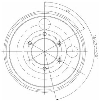
Timing idler gear size, with a right-handed helical direction. Features: The tooth profile is the same as that of a normal gear; some tooth slots have gaps; no Can actively transmit power. Function: It is to make the rotation direction of the fuel injection pump gear and camshaft gear the same as that of the crankshaft timing gear, and the idler gear It is a transitional gear train part that does not change the transmission relationship, but only makes the force distribution of the gear train more reasonable or meets the layout of the entire transmission system. Therefore, it only changes the direction, but does not change the transmission ratio. Material: 20CrMnTi. After carburizing and quenching, this material The surface hardness can reach 58-63 HRC, and the core hardness can reach 32-42 HRC.
Conclusion
This time, we mainly design the gear system of 4105 diesel engine, including crankshaft timing gear, timing idler gear, camshaft gear, fuel injection pump gear, etc., Based on the position of the gear center hole given on the body, the material, modulus, The parameters such as the number of teeth were designed, and the relevant two-dimensional drawings of the gear were drawn. To ensure the correct assembly of each gear, the marking positions of each gear were designed Calculation results indicate the positions of the key slots and marks on the crankshaft, camshaft gear, and oil pump gear
The angle between the camshaft and the crankshaft, the position of the marks on the idler gear, crankshaft gear, and camshaft gear. The design of the 4105 diesel engine gear system provides support for the development of the 4105 diesel engine.Theoretical support.