
Chapter 1: Definition and Composition of Spiral Bevel Gear
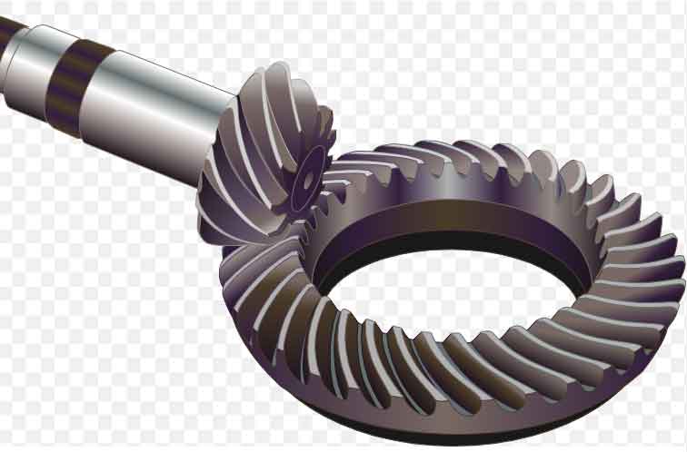
A spiral bevel gear is a type of gear system that consists of two meshing gears with conical and spiral-shaped tooth surfaces. Unlike straight bevel gears, the axes of the gears do not intersect but are offset from each other. This arrangement allows the gears to transmit rotational motion and torque between non-parallel shafts.
Here’s a breakdown of the composition and key features of a spiral bevel gear:
- Driving Wheel: Also known as the input gear, the driving wheel is the gear that is connected to the power source (such as a motor or engine) and initiates the motion. Its tooth surface is conical and spirals along the axis.
- Driven Wheel: Also referred to as the output gear, the driven wheel is the gear that receives the motion and torque from the driving wheel. Its tooth surface is conical and spirals along the axis in a manner that matches the driving wheel’s tooth geometry.
- Tooth Surfaces: The teeth of the spiral bevel gear is designed with a unique spiral curvature that allows them to engage smoothly as they mesh. This design helps in reducing impact forces and noise during the meshing process, making spiral bevel gear suitable for applications where quiet operation is desired.
- Tooth Contact Pattern: Proper tooth contact and engagement are crucial for efficient and reliable gear operation. In spiral bevel gear, the tooth contact pattern changes as the gears rotate, maintaining a consistent and gradual load transfer. This design characteristic contributes to the gear’s ability to handle significant loads without excessive wear or damage.
- Axial Offset: The axes of the driving and driven wheels are not parallel but have an offset, meaning they do not intersect. This offset allows the gears to transmit motion and torque between non-parallel shafts, making spiral bevel gear suitable for applications where input and output shafts are positioned at an angle.
- Applications: Spiral bevel gear is commonly used in various mechanical systems where non-parallel shafts need to transmit motion and torque efficiently. They find applications in industries such as automotive, aerospace, manufacturing machinery, marine, and more.
- Advantages: The main advantages of spiral bevel gear include their ability to transmit high loads, efficient torque transmission, smooth engagement, and the reduction of noise and impact forces during meshing.
- Challenges: Designing and manufacturing spiral bevel gear can be complex due to the unique tooth geometry and the requirement for precise gear cutting and machining processes. Achieving accurate tooth contact patterns and maintaining proper alignment are critical for optimal performance.
In summary, a spiral bevel gear is a specialized type of gear system designed to transmit motion and torque between non-parallel shafts with minimal noise and impact. Its conical and spiral tooth surfaces enable smooth engagement and efficient load distribution, making it a valuable component in various mechanical applications.
Chapter 2: The Structure of Spiral Bevel Gear
The structure of a spiral bevel gear is characterized by its helical tooth surface, which gives the gear its distinctive appearance and functional properties. Here’s a more detailed explanation of the key elements in the structure of a spiral bevel gear:
- Helical Tooth Surface: The most notable feature of a spiral bevel gear is its helical tooth surface. Each tooth has a helix-like shape, which means the tooth surface is not flat but follows a spiral path along the circumference of the gear. This helical design is crucial for achieving smooth engagement and reducing impact and noise during gear meshing.
- Pitch Angle: The pitch angle is the angle between the tooth trace (the curve formed by the intersection of the tooth surface with a plane perpendicular to the gear axis) and a plane perpendicular to the gear axis. In spiral bevel gear, the pitch angle varies as you move along the tooth surface due to its helical nature. The pitch angle affects how the gears mesh and transmit torque.
- Pitch Diameter: The pitch diameter is the diameter of the imaginary pitch circle that the gear’s teeth are developed from. It’s a key parameter used in gear design calculations and defines the gear’s size and pitch.
- Tooth Angle: The tooth angle, also known as the helix angle or spiral angle, is the angle between the tooth trace and an element of the gear axis. It’s the angle at which the helical tooth surface wraps around the gear’s cone. The tooth angle is crucial for ensuring proper meshing and load distribution between the gears.
- Number of Teeth: The number of teeth on the driving and driven wheels can be different in spiral bevel gear. This feature allows flexibility in gear ratio selection and helps accommodate various design requirements.
- Modulus: The modulus is a gear parameter that represents the ratio of the pitch diameter to the number of teeth. It is often used in gear design to ensure compatibility between gears in mesh. In spiral bevel gear, the modulus needs to be matched between the driving and driven wheels to ensure proper meshing and effective power transmission.
- Contact Pattern: As the gears rotate, the contact pattern between the teeth changes. The gradual engagement enabled by the helical tooth design contributes to a larger contact area, distributing the load more evenly and reducing wear.
- Tooth Shape and Profile: The tooth shape and profile are designed to ensure proper meshing, minimize backlash, and provide efficient power transmission. Specialized cutting tools and machining processes are used to create the complex geometry of spiral bevel gear teeth.
In summary, the structure of a spiral bevel gear is characterized by its helical tooth surface, pitch angle, tooth angle, and other parameters. This design allows for gradual engagement, smoother meshing, and reduced impact and noise, making spiral bevel gear suitable for applications where precision, efficiency, and quiet operation are crucial.
Chapter 3: The Characteristics of Spiral Bevel Gear
The key characteristics of spiral bevel gear accurately. Here’s a bit more detail on each of the characteristics you’ve mentioned:
- Smoothness: The helical tooth surface of spiral bevel gear allows for gradual contact during meshing. This feature results in smoother engagement and transmission compared to straight-cut gears. The gradual contact reduces impact forces and noise, making spiral bevel gear an ideal choice for applications where quiet operation is essential.
- High Load-Bearing Capacity: The helical design of the teeth in spiral bevel gear distributes the load over multiple teeth at any given time. This increased tooth engagement and load-sharing capability contribute to their ability to handle higher torque and transmit larger loads. This makes them suitable for applications that require heavy-duty power transmission, such as in industrial machinery and automotive drivetrains.
- Angle Adaptability: One of the unique features of spiral bevel gear is their ability to transmit motion and torque between non-parallel shafts. The offset axes of the gears make them well-suited for applications involving angular transmission, such as in automotive steering systems, where the input and output shafts are not aligned.
- High Efficiency: Spiral bevel gear generally offer high transmission efficiency due to their helical tooth design. The gradual engagement and increased tooth contact area help reduce sliding friction and improve efficiency compared to some other gear types. This efficiency can be especially important in applications where energy conservation and reduced heat generation are priorities.
In addition to the characteristics you’ve mentioned, it’s worth noting that spiral bevel gear is also more complex to manufacture and require precise machining and alignment due to their intricate tooth geometry and the need to maintain proper tooth contact patterns. However, their advantages in terms of smoothness, load capacity, angle adaptability, and efficiency often outweigh these challenges, making them a valuable choice in a wide range of mechanical applications.
Chapter 4: The Design Parameters of Spiral Bevel Gear
some important design parameters for spiral bevel gear. Here’s a bit more detailed information about each parameter:
- Number of Teeth and Pitch: The number of teeth on both the driving and driven gears should be carefully selected to ensure proper meshing and minimize noise and vibration. Additionally, the pitch of the gears should match to ensure smooth engagement and transmission of motion.
- Tooth Angle: The tooth angle, often denoted as β, is a critical parameter that determines the meshing behavior and efficiency of the spiral bevel gear. It’s the angle between the tooth trace (the path of the contact point as the gears rotate) and the gear axis. The choice of tooth angle influences factors like gear strength, load distribution, and efficiency.
- Module: Module (m) is the ratio of the pitch diameter (or circumference) of the gear to π (pi). It affects the size and geometric proportions of the gear. Smaller modules result in smaller gears, while larger modules lead to larger gears. The module is chosen based on design requirements, available space, and desired gear strength.
- Normal Modulus: The normal modulus, sometimes referred to as the normal diametral pitch (Pn), is the ratio of the number of teeth to the pitch diameter of the gear. It influences the angle between the tooth surface and the gear axis. Higher normal modulus values generally lead to stronger gears, as they result in larger teeth with greater contact area. This parameter also affects the gear’s wear resistance.
- Pressure Angle: The pressure angle (α) is the angle between the line perpendicular to the tooth surface and the gear axis. It’s a crucial parameter that affects the distribution of forces and stresses during gear meshing. Common pressure angles are 20° and 30°. A smaller pressure angle can result in smoother meshing and load distribution, while a larger pressure angle might improve gear strength.
These design parameters are interconnected, and their selection involves trade-offs. Engineers need to consider factors like gear strength, load capacity, efficiency, noise, and vibration while designing spiral bevel gear. The optimal values for these parameters depend on the specific application and operational requirements of the gears. Additionally, advanced gear design software and analytical tools are often used to aid in the selection and optimization of these parameters.
Chapter 5: The Manufacturing and Processing of Spiral Bevel Gear
The manufacturing and processing of spiral bevel gear require careful attention to detail and precision. Here’s a more detailed breakdown of the manufacturing process and meshing inspection:
Manufacturing Process:
- Gear Design and Modeling: The process begins with the design of the gear geometry and tooth profiles using specialized software. This involves selecting the appropriate design parameters like the number of teeth, tooth angle, module, etc.
- Gear Blank Preparation: Gear blanks are typically cut from steel or other suitable materials using methods such as forging, casting, or machining. These blanks are then pre-machined to achieve the basic shape and dimensions.
- Machining of Tooth Profiles: The tooth profiles are machined onto the gear blank using techniques like gear hobbing, gear shaping, or gear milling. These methods involve the use of specialized cutting tools to create the precise tooth geometry.
- Heat Treatment: After the tooth profiles are machined, the gears undergo heat treatment to enhance their mechanical properties, such as hardness and toughness. This step is crucial for ensuring the gears can withstand the loads and stresses during operation.
- Gear Finishing: After heat treatment, the gears may undergo additional machining or grinding to achieve the desired surface finish, accuracy, and tolerance levels.
- Assembly and Matching: If the gear is part of a gear set (e.g., a differential), the individual gears are assembled and matched to ensure proper meshing and alignment. This step is critical for achieving smooth and efficient gear operation.
Meshing Inspection:
- Visual Inspection: A visual inspection is the first step to identify any visible defects or irregularities in the gear teeth, such as chips, cracks, or uneven surfaces.
- Dimensional Inspection: Precise measurements are taken using specialized metrology tools to ensure that the gear’s dimensions, tooth profiles, and critical parameters meet the design specifications.
- Gear Meshing Analysis: Computer-aided analysis tools may be employed to simulate the gear meshing process and check for any interference, misalignment, or abnormal behavior. This helps ensure that the gears will mesh correctly during operation.
- Load Testing: In some cases, load testing is performed to assess the gear’s performance under realistic operating conditions. This involves subjecting the gear set to loads and torques similar to those it will experience during operation.
- Noise and Vibration Testing: Gears should undergo testing to evaluate noise and vibration characteristics. Excessive noise or vibration can indicate improper meshing or other issues that need to be addressed.
- Performance Validation: The meshing performance is evaluated to determine whether the gears meet the required efficiency, load capacity, and other performance criteria.
In summary, the manufacturing and processing of spiral bevel gear involve a series of intricate steps, from initial design and machining to heat treatment, assembly, and rigorous inspections. This comprehensive process ensures that the gears are of high quality, meet design specifications, and perform reliably in their intended applications.
Chapter 6: The Characteristics of Spiral Bevel Gear

Some key characteristics of spiral bevel gear accurately. Here’s a bit more detail on each characteristic:
- Smoothness: The helical tooth arrangement in spiral bevel gear allows for gradual engagement as the teeth mesh. This smooth engagement significantly reduces impact and noise during operation, resulting in a quieter and smoother transmission compared to straight-toothed bevel gears.
- High Load-Bearing Capacity: The design of spiral bevel gear includes larger contact areas between the teeth due to the helical angle. This design feature enhances the load-bearing capacity of the gears, making them well-suited for applications that require the transmission of higher torques and loads.
- Angle Adaptability: Spiral bevel gear is capable of transmitting motion between non-parallel intersecting axes. This adaptability to varying angles makes them ideal for applications like automotive steering systems, where the gears are used to transmit motion between the steering wheel (often at an inclined angle) and the steering mechanism.
- High Efficiency: Spiral bevel gear generally exhibit higher transmission efficiency compared to some other gear types, such as worm gears. The helical tooth arrangement allows for multiple tooth pairs to be in contact simultaneously, distributing the load more evenly and resulting in less sliding friction during meshing. This contributes to improved efficiency in power transmission.
- Durability and Strength: The helical tooth geometry and larger contact area not only contribute to smoother operation but also enhance the gears’ durability and strength. The gradual engagement and increased tooth contact distribute loads evenly, reducing the likelihood of high-stress points that can lead to premature wear and failure.
- Precision and Accuracy: The manufacturing process for spiral bevel gear involves precision machining, heat treatment, and careful inspection. This attention to detail results in gears with high accuracy and tight tolerances, ensuring consistent and reliable performance.
- Versatility: Spiral bevel gear find application in a wide range of industries and machinery, including automotive, aerospace, industrial machinery, and more. Their combination of load-bearing capacity, efficiency, and adaptability to non-parallel axes makes them versatile components for various mechanical systems.
In summary, spiral bevel gear possess a unique set of characteristics that make them well-suited for demanding applications where smoothness, high load-bearing capacity, adaptability to angles, high efficiency, durability, and precision are essential.
Chapter 7: The Lubrication and Maintenance of Spiral Bevel Gear
Proper lubrication and maintenance are essential to ensure the longevity and reliable operation of spiral bevel gear. Here’s more information about each aspect:
Lubrication:
Effective lubrication is crucial for the smooth operation of spiral bevel gear. The lubricant forms a thin film between the gear teeth, reducing friction, dissipating heat, and preventing metal-to-metal contact, which can lead to wear and damage. Proper lubrication offers several benefits:
- Friction Reduction: Lubrication minimizes friction between gear teeth, leading to less heat generation and reduced energy losses.
- Wear Prevention: By forming a protective layer, lubrication prevents direct contact between gear surfaces, reducing wear and prolonging gear life.
- Heat Dissipation: Lubricants help dissipate the heat generated during gear meshing, preventing overheating and potential damage.
- Noise Reduction: Adequate lubrication contributes to quieter gear operation by reducing impact and vibration.
The choice of lubricant depends on factors like gear design, operating conditions, load, speed, and temperature. Lubricants should have the appropriate viscosity, additives, and properties to withstand the conditions of the specific application.
Wear and Failure:
Understanding wear patterns and potential failure modes of spiral bevel gear is essential for developing effective maintenance strategies. Some common wear patterns and causes include:
- Abrasive Wear: This occurs due to the presence of foreign particles or contaminants in the lubricant, which can lead to localized wear on the gear teeth surfaces. Regularly changing and filtering the lubricant can help prevent abrasive wear.
- Pitting and Spalling: High loads, inadequate lubrication, or the presence of corrosive elements in the lubricant can cause surface distress, resulting in small pits or spalling on gear teeth. Regular inspections and using appropriate lubricants can mitigate these issues.
- Fretting Wear: This type of wear occurs at the points of contact between the gear teeth due to micro-movements caused by vibration or misalignment. Proper alignment, vibration control, and adequate lubrication can minimize fretting wear.
- Scuffing: It’s a severe form of wear where localized high pressures cause welding and subsequent tearing of the material. Ensuring proper lubrication, load distribution, and material selection can help prevent scuffing.
To develop effective maintenance strategies, regular inspections, vibration analysis, and monitoring of operating conditions are important. Scheduled lubricant changes, alignment checks, and addressing wear issues promptly can extend the life of spiral bevel gear and prevent unexpected failures.
In summary, proper lubrication and maintenance practices are vital for the optimal performance and durability of spiral bevel gear. By using appropriate lubricants, understanding wear patterns, and addressing potential failure modes, you can ensure the gears operate reliably and efficiently over their intended service life.
Chapter 8: The Application Fields of Spiral Bevel Gear
The application fields where spiral bevel gear is widely used. Here’s a bit more detail about each of these application areas:
- Automotive Industry: Spiral bevel gear play a crucial role in the automotive industry. They are used in transmission systems like gearboxes and differentials. In gearboxes, they help transfer power from the engine to the wheels, while in differentials, they allow the wheels to rotate at different speeds, enabling smooth cornering and traction.
- Construction Machinery: Heavy construction equipment, such as excavators, loaders, and bulldozers, rely on spiral bevel gear in their transmission systems. The ability of spiral bevel gear to handle high loads and transmit torque efficiently makes them suitable for these demanding applications.
- Aerospace: In the aerospace sector, spiral bevel gear find use in applications like aircraft landing gear, engine transmission systems, and rotor mechanisms. The high load-bearing capacity and reliability of these gears make them suitable for critical aerospace components.
- Energy Field (Wind Turbines): Wind turbines require gears that can handle the variable and often high torque loads generated by wind conditions. Spiral bevel gear is employed in the transmission systems of wind turbines to efficiently convert the rotational energy of the wind into electrical power.
- Industrial Machinery: Spiral bevel gear is widely used in various industrial machinery applications. They can be found in equipment such as machine tools, printing presses, textile machinery, and more. These gears facilitate the transmission of power and motion within these industrial systems.
- Marine Applications: Spiral bevel gear is utilized in marine propulsion systems, where they play a role in transmitting power from engines to propellers. They are designed to withstand the corrosive effects of seawater and provide efficient power transmission.
- Railway Industry: Spiral bevel gear is used in railway applications, particularly in the drivetrains of locomotives and railcars. They help transfer power from the engines to the wheels, enabling the movement of trains.
- Mining Equipment: Mining equipment, such as large haul trucks and drilling machinery, relies on spiral bevel gear for their robustness and ability to handle heavy loads in challenging environments.
- Medical Equipment: In some medical devices, spiral bevel gear is employed to transmit motion and power. Their precision and reliability are essential for accurate and consistent performance in medical applications.
The versatility of spiral bevel gear, along with their ability to handle high loads, transmit power efficiently, and adapt to different angles, makes them suitable for a wide range of industries and applications where precision and reliability are critical.