
Spiral bevel gear transmission is widely used in high-speed and heavy-duty gear transmission systems with intersecting transmission of two axes, such as aviation, automobile, machine tool and so on. However, due to the particularity of spiral bevel gear, there are great differences between spiral bevel gear and spur cylindrical gear in the processing of tooth profile and tooth direction of gear surface and the adjustment of gear assembly position in assembly link. The axial, circumferential and radial component forces produced by the working of spiral bevel gear will change the original assembly position of the gear pair and the meshing contact area of the gear pair, which will affect the bearing capacity and working quality of the gear pair. During the processing, assembly and adjustment of the tooth surface of the gear pair, the tooth shape and tooth direction of the tooth surface shall be designed and corrected according to the local conjugate principle, and the meshing contact area shall be checked by brushing colorant at various working positions, To avoid possible edge contact due to the change of contact area caused by assembly error and force change of transmission system. Therefore, in the design of spiral bevel gear, after completing the selection of transmission parameters, accuracy design and load-bearing capacity check, the working meshing position of spiral bevel gear pair under various x conditions (such as starting working state, long-term working state, etc.) shall be analyzed according to the local conjugate contact method, The instruction of feeding contact area during processing and assembly of spiral bevel gear pair is compiled for testing during processing and assembly of spiral bevel gear.
The following conclusions can be drawn:
- It is feasible to control the meshing contact area of spiral bevel gear tooth surface with the process method of “three coordinate detection instead of meshing coloring inspection”.
- For the detection of meshing contact area in the processing and assembly of spiral bevel gear, the gear grinding process adopts “three-dimensional detection of tooth surface is the main, supplemented by meshing coloring inspection”, and the gear milling process adopts “three-dimensional detection instead of meshing coloring detection” It is feasible to adopt the process method of “fixed distance assembly supplemented by coloring inspection” in the assembly process.
- This process method can also be used to detect the meshing area of the tooth surface of straight bevel gear.
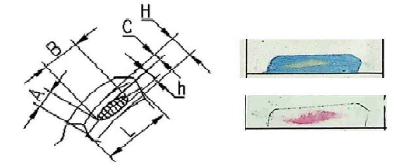
Generally, due to the complex working conditions and calculation of spiral bevel gear, the meshing instructions are mostly determined by the metal wear marks after the spiral bevel gear pair works. The meshing instructions have requirements for the installation position of spiral bevel gear pair grinding and assembly meshing inspection area, as well as the current situation, size, position layout and side clearance of colored contact area marks. The requirements for the shape and size of the impression in the meshing contact area of the meshing manual are shown in Figure la.