
For the design of hypoid gear pair blank with small number of teeth and large reduction ratio, the axle intersection angle between large and small wheels is determined according to the service conditions of the designed hypoid gear Σ, The number of teeth Z2 and Z1 of the large and small wheels, the rotation direction and offset distance E of the large and small wheels. The number of small teeth of a few hypoid gears with large reduction ratio is less than 5, and the sum of teeth of gear pair is greater than 40. The determination of the rotation direction of large and small wheels requires that the axial force generated by the two wheels in the meshing process makes the two wheels have the trend of pushing away from each other; The offset mode of the small wheel shall be selected by increasing the strength of the small wheel.
The hypoid gear with small number of teeth and large reduction ratio is designed and calculated according to the way that the shaft intersection angle is 90 °, the large wheel rotates right and the small wheel rotates left downward.
When determining the pitch cone of hypoid gear with small number of teeth and large reduction ratio, it is necessary to determine the position of the node on the pitch cone first. According to the geometric characteristics of hypoid gear, it is necessary to determine the node radius R2 of large wheel and the helix angle of small wheel β 1 and offset angle of small wheel shaft section relative to η These three parameters determine the location of the node. Next, the determination method of these three parameters is discussed first.
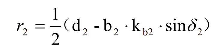
Node radius R2 and tooth width B2 of hypoid gear big wheel, pitch circle diameter D2 and pitch cone angle of big wheel δ 2 relevant. In order to increase the design flexibility of hypoid gear with small number of teeth, the design node is not necessarily taken at the midpoint of tooth width. In view of this, the longitudinal displacement coefficient, that is, the tooth width coefficient kb2, is introduced, and the width between the node and the big end is B2 kb2。 That is, when kb2 is taken as 0.5, the node is located at the midpoint of the tooth width. In this way, the node radius R2 of the big wheel is:
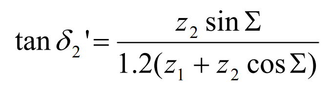
According to the hypoid gear, the tooth surface width B2 of the large wheel shall not be greater than 10 D2 / Z2 and 1 / 3 of the outer cone distance of spiral bevel gear under the same conditions, and the pitch cone angle is slightly less than that of the large wheel of spiral bevel gear under the same conditions. The pitch cone angle of the large wheel used in the initial calculation can be approximately calculated by the following formula:
The helix angle of the hypoid gear small wheel should be given in advance, and its selection can be determined according to the limiting conditions in Section 2.1. For example, in the calculation example of the tooth ratio of 4:41, the helix angle of the hypoid gear small wheel β 1 takes 59 °.
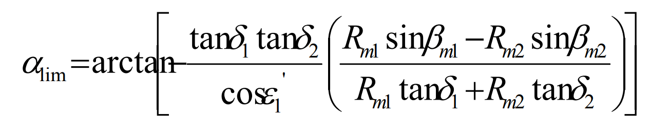
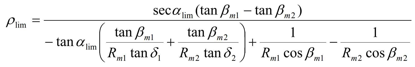
In order to adjust the shape and meshing condition of tooth surfaces on both sides and the design of hypoid gears with small number of teeth and large reduction ratio, it is necessary to introduce the influence coefficient falim of limit pressure angle (generally, the value of falim is taken as 1). Generally, increase the limit pressure angle on the working side and reduce the limit pressure angle on the non working side. When the limit pressure angle changes, the limit radius of curvature changes. The limit pressure angle and limit radius of curvature of hypoid gear pinion can be determined respectively by the following formula:
Offset angle of pinion shaft section of hypoid gear η It is related to the radius r0 of the cutting cutter head, which is determined according to the pitch diameter of the outer end of the large wheel of hypoid gear.
After these parameters are determined, a series of iterative derivation is carried out by using the calculation formula of hypoid gear to calculate the limit normal radius of curvature R ‘, and the pitch cone parameters obtained last time are the actual pitch cone parameters.
Calculate the distance between the node of the hypoid gear big wheel along the axis of the big wheel and the designed intersection point, the distance between the intersection point and the cone vertex of the big wheel pitch, and the distance between the intersection point and the cone vertex of the small wheel pitch. After these three parameters are fully determined, the pitch cone parameters of the hypoid gear are fully determined.