
In the field of gear manufacturing, especially for automotive rear axle drives, the demand for efficient and high-precision gear milling processes is ever-growing. Cycloid bevel gears, known for their smooth transmission and low noise, have gained significant attention due to their continuous indexing double-sided processing method. However, the advanced gear milling technology and equipment for these gears are predominantly monopolized by a few international companies, making them costly for many enterprises. As a researcher focused on advancing gear milling techniques, I embarked on developing an economical two-axis CNC formate milling machine specifically for cycloid bevel gears. This initiative aims to provide a cost-effective alternative for formate processing of large gears, thereby reducing production costs while maintaining precision. The core of this work lies in establishing mathematical models, deriving machine adjustment parameters, and implementing CNC programming to control the gear milling process. Throughout this article, I will delve into the principles, machine development, and experimental validation, emphasizing the keyword “gear milling” to highlight its centrality in modern manufacturing.
The formate gear milling process for cycloid bevel gears is based on the hypothetical crown gear principle, where the cutter head and workpiece rotate synchronously at a fixed ratio to achieve continuous indexing and generate extended epicycloidal tooth lines. In this method, the cutter head, equipped with multiple sets of inner and outer blades, rotates clockwise, while the workpiece rotates in the opposite direction. By considering the workpiece stationary, the relative motion of the cutter head mimics a circle rolling purely on a base circle attached to the workpiece, tracing an extended epicycloid on the pitch plane. Each set of blades cuts both the convex and concave sides of a tooth slot in one rotation, enhancing gear milling efficiency. For large gears with a transmission ratio \(i_{12} \geq 3\) or a pitch cone angle \(\delta_2 \geq 60^\circ\), the tooth profile approximates a straight line, making formate processing ideal to boost productivity. The fundamental mathematical model for this gear milling approach involves defining coordinate systems and motion relationships, as illustrated in prior studies. Let \(S_e\) represent the cutter head coordinate system, \(S_2\) the workpiece coordinate system, and \(\beta\) the rotation angle of the cutter head. The workpiece rotation angle \(\phi_2\) is governed by the indexing ratio:
$$ \phi_2 = \frac{z_0 \beta}{z_2} $$
where \(z_0\) is the number of blade sets on the cutter head, and \(z_2\) is the number of teeth on the workpiece. This equation ensures synchronized motion during gear milling, critical for achieving accurate tooth geometry. Additional parameters include the vertical cutter distance \(V\), horizontal cutter distance \(H\), and workpiece installation angle \(\delta_M\), which are derived from machine adjustments. The formate gear milling model simplifies the process by focusing on maintaining a fixed speed ratio between the cutter and workpiece, eliminating the need for complex rocking mechanisms. This foundational model sets the stage for developing a dedicated CNC machine, optimizing gear milling operations for cycloid bevel gears.
Building upon the basic mathematical model, I designed a two-axis CNC formate milling machine tailored for cycloid bevel gear milling. The machine structure comprises a cutter head assembly, workpiece spindle, sliding saddle, and machine base, with a unique drum mechanism to enhance rigidity. Unlike traditional machines with rocking platforms, this design incorporates a drum where the cutter head is eccentrically mounted. The vertical cutter distance is adjusted by rotating the drum, while the horizontal cutter distance is controlled by moving the X-direction slide. This configuration simplifies adjustments to three key parameters: drum rotation angle, X-slide position, and workpiece installation angle. During gear milling, CNC programs drive the machine motions, automating the cutting process and improving operational efficiency. The servo motors for the cutter head and workpiece spindles enable precise联动, ensuring continuous indexing essential for cycloid gear milling. The machine mathematical model, depicted in Figure 4 of the original work, ensures equivalence with the basic model by aligning the relative positions between the cutter and workpiece. Let \(O_e0\) be the initial cutter center, \(O_0\) the drum center, and \(E\) the eccentric distance of the cutter head. The drum rotation angle \(\Phi\) and X-slide displacement \(\Delta X\) are calculated as follows:
$$ \Phi = 180^\circ + \arcsin\left(\frac{V}{E}\right) $$
$$ \Delta X = (S_p + L) \cos \delta_M – H – E – E \cos(\Phi – 180^\circ) $$
Here, \(S_p\) is the horizontal workpiece position, \(L\) is the distance from the pivot point to the workpiece spindle face, and other terms align with standard gear milling parameters. These formulas enable accurate machine setup for gear milling, ensuring the cutter path matches the theoretical tooth surface. The machine’s compact design and reduced degrees of freedom make it an economical solution for formate gear milling, particularly in mass production scenarios where cost-effectiveness is paramount. To illustrate the machine parameters, consider the following table summarizing key adjustment variables for gear milling:
| Parameter | Symbol | Description | Typical Range |
|---|---|---|---|
| Drum Rotation Angle | \(\Phi\) | Adjusts vertical cutter distance | 150° to 210° |
| X-Slide Displacement | \(\Delta X\) | Adjusts horizontal cutter distance | 300 mm to 400 mm |
| Workpiece Installation Angle | \(\delta_M\) | Sets workpiece orientation | 0° to 90° |
| Vertical Cutter Distance | \(V\) | Distance from cutter to摇台 center | 100 mm to 200 mm |
| Horizontal Cutter Distance | \(H\) | Horizontal offset of cutter | 50 mm to 150 mm |
This table highlights the critical adjustments in gear milling, ensuring precise control over tooth geometry. The development of this machine emphasizes simplicity and affordability, addressing the gap in the market for dedicated formate gear milling equipment. The integration of CNC technology further enhances repeatability and accuracy in gear milling operations.
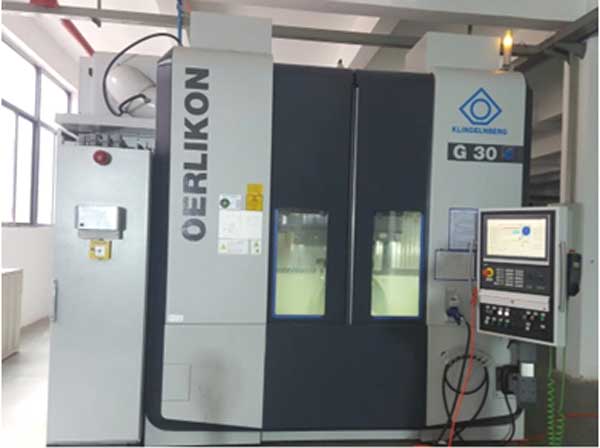
To implement the gear milling process on the developed machine, I utilized the Siemens 828D CNC system, leveraging its electronic gearbox (EGB) and synchronous programming functions. The EGB feature allows the workpiece spindle (B-axis) to follow the cutter head spindle (A-axis) at a fixed ratio, enabling continuous indexing crucial for cycloid gear milling. In this setup, the A-axis is designated as the main spindle for speed control, while the B-axis synchronizes via EGB to maintain the gear milling motion. Synchronous programming is employed to coordinate the cutting feed and retract movements without disrupting the联动 relationship. The CNC program, written in Siemens syntax, controls the gear milling sequence: approaching the start position, engaging electronic gearbox, initiating cutter rotation, executing cutting feeds, and retracting after dwell time. Key program segments include defining EGB with parameters for speed ratio, using WHENEVER statements for synchronized motions, and managing axis positions. For instance, the speed ratio between cutter and workpiece is set based on blade sets and tooth count, ensuring precise indexing during gear milling. The program also incorporates variables for feed rates, depth increments, and dwell times, optimizing the gear milling cycle for efficiency and surface quality. Below is a simplified representation of the gear milling logic in pseudo-code:
CNC Program Structure for Gear Milling:
- Move to approach position at rapid feed.
- Activate electronic gearbox with ratio \(R_{11}/R_{12}\) (derived from \(z_0\) and \(z_2\)).
- Start cutter rotation at specified spindle speed.
- Execute synchronized feed motions in steps: roughing, finishing, and dwell.
- Retract cutter and cancel synchronization.
- Deactivate electronic gearbox and end program.
This structured approach ensures seamless control over gear milling operations, reducing manual intervention and enhancing consistency. The use of EGB in gear milling allows for dynamic adjustments, accommodating variations in gear design without hardware changes. Additionally, the program’s modularity facilitates adaptation to different gear milling tasks, making the machine versatile for small-batch production. The integration of CNC programming with the machine’s mechanical design exemplifies a holistic approach to advanced gear milling, where software and hardware synergize to achieve precision.
To validate the machine’s performance in gear milling, I conducted a cutting experiment using a cycloid hypoid gear pair with an 8/39 tooth configuration. The large gear was processed via formate gear milling on the developed machine, with geometric parameters and cutting settings detailed in tables. The gear pair specifications include a shaft angle of 90°, normal module of 3.8929 mm, and spiral angles of 50° for the pinion and 29.5686° for the gear. For the large gear gear milling, the cutter head model was 17-88, with radial cutter distance of 118.9134 mm and angular cutter position of 47.2004°. The machine adjustments were computed from the basic parameters: drum rotation angle of 149.12°, X-slide position of 335.691 mm, and workpiece installation angle of 71.0984°. During gear milling, the cutter head and workpiece rotated at a synchronized ratio to ensure continuous indexing, producing the extended epicycloidal tooth lines. The cutting experiment demonstrated stable motion and chip formation, indicating robust machine dynamics. Post-processing, the gear was inspected for tooth surface accuracy using a Klingelnberg P65 measuring machine, with results showing deviations within 0.01 mm. This confirms that the gear milling process achieved close conformity to the theoretical tooth surface. Furthermore, a rolling test was performed to assess contact patterns, revealing alignment with designed contact areas, thus validating the gear milling accuracy and machine model. Below, tables summarize the gear parameters and gear milling outcomes:
| Parameter | Pinion | Gear (Large) |
|---|---|---|
| Number of Teeth | 8 | 39 |
| Hand of Spiral | Left | Right |
| Shaft Angle (°) | 90 | |
| Normal Module at Ref. Point (mm) | 3.8929 | |
| Spiral Angle at Ref. Point (°) | 50 | 29.5686 |
| Pressure Angle (°) | 20 | |
| Face Width (mm) | 38.8 | 32.18 |
| Whole Depth (mm) | 8.759 | |
| Addendum (mm) | 5.8967 | 1.889 |
| Pitch Cone Angle (°) | 17.7897 | 71.0984 |
| Parameter | Value |
|---|---|
| Cutter Head Model | 17-88 |
| Radial Cutter Distance (mm) | 118.9134 |
| Angular Cutter Position (°) | 47.2004 |
| Installation Angle (°) | 71.0984 |
| Vertical Workpiece Position (mm) | 0 |
| Workpiece Position Correction (mm) | 5.815 |
| Machine Center Correction (mm) | -2.0038 |
| Roll Ratio | 0 |
The success of this gear milling experiment underscores the machine’s capability to produce high-quality cycloid bevel gears with minimal error. The tooth surface errors, measured along the profile and lead directions, were consistently below 0.01 mm, as shown in a deviation plot. This level of precision meets industrial standards for gear milling, ensuring reliable performance in automotive applications. The rolling test contact pattern exhibited good centrality and size, matching simulations from KIMOS software, which further validates the gear milling process. These results demonstrate that the developed machine offers a viable, economical solution for formate gear milling of large cycloid bevel gears, potentially replacing expensive imported equipment in production lines.
In conclusion, the development of a two-axis CNC formate milling machine for cycloid bevel gears represents a significant advancement in gear milling technology. By establishing fundamental mathematical models and deriving machine adjustment parameters, I have created a system that simplifies the formate gear milling process while maintaining high precision. The machine’s design, featuring a drum mechanism and servo-driven axes, reduces complexity and cost, making gear milling more accessible to manufacturers. The CNC programming approach, utilizing electronic gearbox and synchronous functions, ensures accurate control over cutting motions and indexing. Experimental validation through gear milling of an 8/39 gear pair confirmed that the machine achieves tooth surface errors within 0.01 mm and produces contact patterns aligned with theoretical designs. This proves that the machine’s gear milling performance meets engineering requirements for automotive transmissions. Future work could focus on expanding the machine’s capabilities to include dry cutting or adapting it for other gear types, further enhancing its versatility in gear milling applications. Overall, this project highlights the potential for innovative, cost-effective solutions in gear milling, contributing to the evolution of manufacturing technologies.
Throughout this article, the term “gear milling” has been emphasized to reflect its centrality in the discussed processes. From mathematical modeling to CNC implementation and experimental verification, gear milling serves as the backbone of producing cycloid bevel gears efficiently. The integration of tables and formulas, such as those for machine adjustments and gear parameters, provides a comprehensive overview of the technical aspects involved in gear milling. As industries continue to seek affordable and precise manufacturing methods, advancements in gear milling machines like the one described here will play a crucial role in shaping the future of gear production. By reducing reliance on expensive imported equipment, such developments empower local industries to enhance their competitiveness in the global market, ultimately driving innovation in gear milling and related fields.