
The precision rotary vector reducer is a cornerstone of modern robotic joints, directly determining the dynamic performance, load capacity, and positioning accuracy of industrial robots. Its superiority lies in its compact two-stage design, combining a primary involute planetary stage with a secondary cycloidal pin-cycloid planetary stage. The dynamic transmission characteristics of the entire RV reducer system are profoundly influenced by the behavior of its core components, with the cycloidal gear playing a pivotal role. The vibration modal characteristics of this gear are critical for understanding system resonance, noise generation, and long-term reliability. Traditional analyses often simplify the boundary conditions, examining the cycloidal gear in free or simple bearing-supported states. However, its actual operational state is defined by simultaneous constraints from the support bearings and its continuous meshing engagement with the needle pins and the pin shell. This work focuses on analyzing the vibration modal characteristics of the cycloidal gear within a high-precision rotary vector reducer, specifically considering this realistic meshing state, and compares the results with those from free and bearing-constrained conditions.
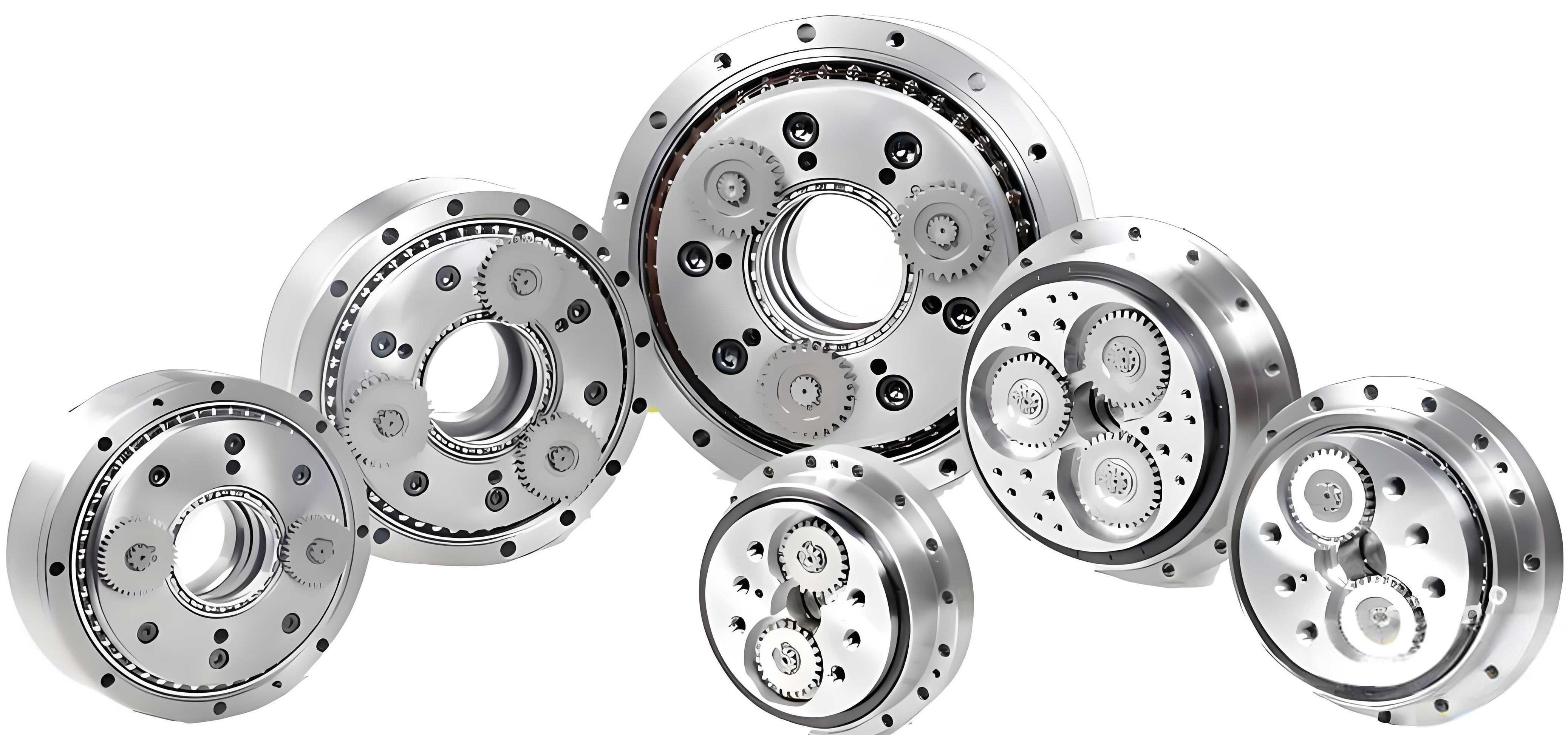
The operational principle of the rotary vector reducer is key to understanding the loading environment of the cycloidal gear. In a typical configuration with a fixed pin shell, motion is transmitted as follows: input rotation drives the input gear shaft, which meshes with multiple planetary gears to achieve the first-stage speed reduction. The planetary gears are mounted on crankshafts, which convert this rotation into an eccentric motion. This eccentric motion drives the cycloidal gears, causing them to mesh with the stationary needle pins housed in the pin shell, thereby accomplishing the second, and more significant, stage of speed reduction. The final output is taken from the planet carrier (output flange) connected to the cycloidal gears via rollers. This mechanism subjects the cycloidal gear to a complex state of loading involving bearing reactions from the crankshaft and dynamic contact forces from multiple needle pins simultaneously.
The foundation of dynamic analysis lies in understanding the system’s natural frequencies and mode shapes, which are intrinsic properties determined by mass and stiffness distribution. For a continuous structure like the cycloidal gear, its free vibration is governed by the following general equation of motion:
$$ [M]\{\ddot{x}\} + [K]\{x\} = \{0\} $$
where $[M]$ is the mass matrix, $[K]$ is the stiffness matrix, $\{\ddot{x}\}$ is the acceleration vector, and $\{x\}$ is the displacement vector. The solution to this eigenvalue problem yields the natural frequencies ($\omega_n$) and corresponding mode shapes ($\{\phi_n\}$):
$$ \left( [K] – \omega_n^2 [M] \right) \{\phi_n\} = \{0\} $$
The stiffness matrix $[K]$ is drastically affected by the applied constraints. A “free” condition implies no stiffness at the boundaries, while “bearing constraints” introduce localized stiffness at the bearing bores. The “meshing state” introduces a distributed, nonlinear contact stiffness along the engaged tooth flanks, fundamentally altering the system’s global stiffness characteristics and, consequently, its modal properties.
To investigate this, a finite element analysis (FEA) was conducted on a model representative of a common rotary vector reducer size. The cycloidal gear, needle pins, and pin shell were modeled in detail. The material properties assigned are standard for such components and are summarized in Table 1.
| Component | Material | Density, $\rho$ (kg/m³) | Young’s Modulus, $E$ (GPa) | Poisson’s Ratio, $\mu$ |
|---|---|---|---|---|
| Cycloidal Gear | GCr15 Bearing Steel | 7810 | 208 | 0.30 |
| Needle Pins | GCr15 Bearing Steel | 7810 | 208 | 0.30 |
| Pin Shell | QT450 Ductile Iron | 7000 | 173 | 0.30 |
The analysis proceeded in three distinct phases to isolate the effect of constraints on the modal response of the cycloidal gear. The first phase involved a modal analysis of the cycloidal gear in a completely free state, with no boundary conditions applied. This serves as a baseline, representing the inherent dynamic properties of the gear’s geometry and material alone. A free mesh was generated with sufficient refinement to capture the geometry of the teeth and bearing bores accurately. The resulting first ten natural frequencies and their dominant mode shape descriptions are presented in Table 2. As expected, the modes involve pure bending, torsion, and stretching of the gear body, with relatively low frequencies due to the lack of any restraining stiffness.
| Mode Order | Natural Frequency (Hz) | Dominant Mode Shape Description |
|---|---|---|
| 1 | 2157.8 | Bending along the Z-axis |
| 2 | 2279.1 | Bending around the X-axis |
| 3 | 3480.5 | Stretching along the X-axis |
| 4 | 5341.2 | Bending around the X-axis (higher order) |
| 5 | 5429.5 | Bending in the XOY plane |
| 6 | 6593.4 | Stretching in the XOY plane |
| 7 | 6944.0 | Torsion around the X-axis |
| 8 | 7826.2 | Torsion around the Y-axis |
| 9 | 9480.0 | Bending in the XOY plane (complex) |
| 10 | 9694.8 | Bending in the XOY plane (complex) |
The second phase introduced a more realistic boundary condition by constraining the inner surfaces of the two bearing bores. In a real rotary vector reducer, these bores interface with needle roller bearings on the crankshafts, providing radial support but allowing rotation. For modal analysis, which is a linear perturbation around a fixed state, these interfaces are simulated as cylindrical support constraints, which restrain translational motion in the radial direction but allow axial and rotational degrees of freedom. This significantly increases the system’s stiffness compared to the free state. The results, shown in Table 3, confirm this stiffening effect, with all natural frequencies experiencing a substantial increase. The mode shapes also shift, now involving more localized deformation around the stiffened bore regions and different global patterns.
| Mode Order | Natural Frequency (Hz) | Dominant Mode Shape Description |
|---|---|---|
| 1 | 2757.7 | Oscillation/Sway along the Y-axis |
| 2 | 2799.9 | Torsion/Rocking along the Y-axis |
| 3 | 4807.7 | Bending around the X-axis |
| 4 | 5293.7 | Oscillation in the XOY plane |
| 5 | 6175.7 | Oscillation in the XOY plane (different phase) |
| 6 | 7373.5 | Torsion around the Z-axis |
| 7 | 8533.4 | Torsion in the XOY plane |
| 8 | 9056.9 | Stretching along the Z-axis |
| 9 | 10233.0 | Stretching along the X-axis |
| 10 | 10272.0 | Stretching along the Z-axis (higher order) |
The third and most critical phase models the true working condition of the cycloidal gear within the rotary vector reducer assembly: the meshing state. This requires modeling the cycloidal gear, the needle pins, and the pin shell as an assembly. The pin shell is fixed at its mounting holes. The cycloidal gear retains its bearing constraints at the bores. Crucially, “bonded” or linear contact constraints are defined between the flanks of the cycloidal gear teeth and the surfaces of the needle pins (which are themselves fixed within the pin shell for this static modal analysis). This simulates the instantaneous stiffness provided by the multiple teeth in contact during operation. The meshing interaction introduces a distributed stiffness around the periphery of the gear, radically changing its dynamic behavior. The finite element model for this state is necessarily larger and more complex, as it includes the contact definitions between multiple components. The results, tabulated in Table 4, reveal a dramatic further increase in the natural frequencies across all modes. The first mode, for instance, jumps from 2757.7 Hz (bearing constraint) to 3114.7 Hz. The mode shapes in this condition are distinct from the previous cases; deformation is heavily suppressed in the region of the meshing teeth, and the dominant vibration patterns shift to those that involve deflection in directions orthogonal to the strong radial stiffness provided by the meshing.
| Mode Order | Natural Frequency (Hz) | Dominant Mode Shape Description |
|---|---|---|
| 1 | 3114.7 | Bending along the Y-axis (perpendicular to primary mesh stiffness) |
| 2 | 3120.8 | Torsion/Rocking along the Y-axis |
| 3 | 4921.2 | Bending along the X-axis |
| 4 | 5983.5 | Torsion in the XOY plane |
| 5 | 7307.5 | Bending in the XOY plane |
| 6 | 8221.4 | Torsion around the Z-axis |
| 7 | 9318.6 | Stretching along the Z-axis |
| 8 | 10170.0 | Torsion along the Z-axis |
| 9 | 10591.0 | Bending along the Z-axis |
| 10 | 11832.0 | Stretching along the X-axis |
The comparative effect of the three constraint conditions on the natural frequencies is best visualized by plotting them together. The trend is unequivocal: each successive addition of realistic constraint stiffness—first from the bearings, then from the meshing teeth—elevates the entire frequency spectrum of the cycloidal gear. This has profound implications for the design and analysis of the rotary vector reducer. For instance, an excitation source (like gear mesh frequency harmonics from the first stage or motor ripple) that might have been concerningly close to a natural frequency in the free or bearing-only model could be completely non-problematic in the actual meshing state, as the relevant mode has shifted to a much higher frequency. Conversely, relying on simplified models could lead to unnecessary over-design or, worse, a failure to identify a potential resonance in the real assembly.
The mathematical rationale for this frequency shift can be conceptualized by considering an idealized simplified model. The meshing action effectively adds a series of distributed linear spring elements around the gear’s perimeter. If we model the gear body as a rigid ring of mass $m$ supported by an effective bearing stiffness $k_b$ and an effective meshing stiffness $k_m$, the approximate natural frequency for a translational mode becomes:
$$ f_n = \frac{1}{2\pi} \sqrt{\frac{k_b + k_m}{m}} $$
It is clear that $f_n$ increases as the total stiffness $(k_b + k_m)$ increases. The meshing stiffness $k_m$ in a rotary vector reducer is typically very high due to the multiple teeth sharing the load, often surpassing the bearing stiffness $k_b$, leading to the significant frequency elevation observed. For torsional and other complex modes, the effect is similar but involves the distribution of stiffness modifying the system’s mass and stiffness matrices in a more complex manner.
Furthermore, the change in mode shapes is equally important. In the free state, deformation is global. With bearing constraints, nodes (points of minimal displacement) form near the bores. In the meshing state, large sections of the gear’s outer rim become virtually locked due to contact, forcing the deformation patterns into new configurations, often involving more bending of the central web or axial modes. This altered dynamic deflection profile influences how the gear interacts with the pins under dynamic loads, affecting load distribution, stress fluctuations, and ultimately, the transmission error and noise generation of the rotary vector reducer.
In conclusion, the modal vibration characteristics of the cycloidal gear are not fixed properties but are highly dependent on its constrained boundary conditions. This analysis demonstrates that considering only the free or even the bearing-supported state provides an incomplete and non-conservative picture for a rotary vector reducer. The operational meshing state, which incorporates the combined stiffness from the support bearings and the engaged needle pins, results in significantly higher natural frequencies and distinctly different mode shapes. Therefore, for accurate dynamic characterization, fault diagnosis, noise-vibration-harshness (NVH) prediction, and structural optimization of a rotary vector reducer, it is essential to perform modal and subsequent dynamic analyses under conditions that faithfully represent the meshing engagement. This approach forms a vital foundation for advancing the design of high-performance, low-noise, and highly reliable rotary vector reducers essential for precision robotics and automation systems. Future work could extend this analysis to include nonlinear time-varying meshing stiffness, the effects of manufacturing errors like profile modifications, and the coupled dynamics between the two cycloidal gears and the planet carrier in a full system-level model of the rotary vector reducer.