
The precise manufacture of cyclo-palloid bevel gears, particularly those conforming to the Klingelnberg tooth system, is critical for high-load transmission applications in industries such as aerospace, heavy machinery, and automotive. The complexity of their tooth geometry, characterized by a curved lengthwise tooth form (epicycloidal) and constant tooth depth, necessitates sophisticated multi-axis gear cutting processes. Ensuring the correctness of design parameters and machine settings prior to physical manufacturing is paramount to avoid defects like undercut, top cutting, or improper tooth contact patterns. This research focuses on the development of a comprehensive computer-aided gear cutting simulation system. The system aims to generate accurate three-dimensional solid models of the gears through a virtual machining process, thereby providing a powerful tool for verifying both geometric design and the intricate machine setup parameters essential for successful gear cutting.
Fundamental Theory and Simulation Rationale
The machining principle for Klingelnberg-type cyclo-palloid bevel gears is based on the concept of a virtual generating crown gear or planar generating gear. The actual cutting is performed by a face milling cutter head, but its action is kinematically equivalent to a meshing process between the workpiece and this imaginary planar generating gear. The cutter head comprises alternate inside and outside blades. As the cutter rotates and the workpiece is rolled relative to the imaginary generating gear, the straight-line cutting edges of the blades generate the tooth flanks of the planar gear. The tooth trace on this generating gear is an extended epicycloid. The final tooth surface on the manufactured bevel gear is the envelope of this generating surface throughout the relative rolling motion.
The core idea of the gear cutting simulation is to replicate this physical material removal process in a digital environment using Boolean operations between solid models. Instead of simulating the complex motion of individual cutter blades, the simulation operates at a higher kinematic level: it simulates the interaction between a solid model of the workpiece blank and a solid model representing the tooth of the virtual planar generating gear. The generating gear tooth is itself created based on the known geometry of the cutter blades and the epicycloidal path. The material removed during virtual gear cutting corresponds precisely to the volume of intersection between the workpiece blank and the generating gear tooth at successive positions throughout the simulated roll cycle. Subtracting this intersection volume from the blank yields the machined gear tooth space.
Mathematical Foundation and Simulation Algorithm
The simulation algorithm is built upon precise mathematical models for the generating surface, machine kinematics, and solid Boolean operations. The following outlines the key mathematical components and the stepwise simulation procedure.
1. Geometry of the Generating Surface
The generating surface $$\Sigma_p$$ is a ruled surface formed by the straight-line cutting edge of a blade as it moves along the extended epicycloidal path on the generating plane. For a right-hand generating gear tooth, the convex flank (generated by an outside blade) and concave flank (generated by an inside blade) can be defined parametrically. Let $$u$$ be the parameter along the blade edge and $$\theta$$ be the rolling parameter. A point on the generating surface can be expressed as:
$$ L(u, \theta) = O_g + \mathbf{T}(\theta) \cdot (\mathbf{R}(\theta) \cdot P_{blade}(u)) $$
Where:
- $$O_g$$ is the origin of the generating gear coordinate system.
- $$\mathbf{T}(\theta)$$ is the translation matrix representing the center of the rolling circle.
- $$\mathbf{R}(\theta)$$ is the rotation matrix associated with the roll angle $$\theta$$.
- $$P_{blade}(u)$$ is a point on the straight-line cutting edge in the blade coordinate system.
The specific form of these matrices and vectors is derived from the machine settings: cutter radius $$r_c$$, blade angle $$\alpha$$, point radius $$r_p$$, and the basic circle radius $$\rho$$ governing the epicycloid. The fundamental geometric parameters for a typical gear set are summarized in Table 1.
| Parameter | Symbol | Pinion | Gear |
|---|---|---|---|
| Number of Teeth | $$z$$ | 12 | 36 |
| Face Module | $$m_n$$ | 18.75 mm | |
| Shaft Angle | $$\Sigma$$ | 90° | |
| Mean Spiral Angle | $$\beta_m$$ | 30° | -30° |
| Mean Pressure Angle | $$\alpha_n$$ | 20° | |
| Face Width | $$b$$ | – | 110 mm |
| Pitch Angle | $$\delta$$ | 18.4349° | 71.5651° |
2. Kinematics of the CNC Gear Cutting Machine
Modern gear cutting for these gears is performed on multi-axis CNC machines like the Klingelnberg C100 U. The simulation must replicate the coordinated motion of all machine axes. The essential axes involved in the gear cutting process and their functions are listed in Table 2.
| Axis | Type | Function in Gear Cutting Simulation |
|---|---|---|
| A (Cutter Spindle) | Rotary | Rotation of the generating gear/cutter head. |
| B (Workpiece Spindle) | Rotary | Rotation of the gear blank. |
| C (Tilt) | Rotary | Sets the root angle of the workpiece. |
| X, Y, Z | Linear | Position the blank relative to the cutter; Y and Z simulate the generating roll motion. |
| A1 (Swivel) | Rotary | Adjusts the cutter head swivel angle. |
The synchronized relationship between the workpiece rotation $$\phi_w$$, the generating gear (cutter) rotation $$\phi_c$$, and the linear axis positions (Y, Z) that emulate the roll of a mechanical cradle is governed by the fundamental kinematic equation of generation:
$$ \phi_w = \frac{z_p}{z_w} \phi_c + \phi_{offset} $$
where $$z_p$$ is the number of teeth of the planar generating gear (often equal to the number of cutter blade groups), and $$z_w$$ is the number of teeth of the workpiece. The linear axes Y and Z follow a predefined relationship with $$\phi_c$$ to create the exact relative rolling motion between the imaginary generating gear and the workpiece.
3. Stepwise Simulation Algorithm
The gear cutting simulation procedure is implemented as a discrete process over small increments of the generating roll angle $$\Delta\phi_c$$. The core of the algorithm relies on iterative Boolean intersection and union operations. The detailed steps are as follows:
Step 1: Model Creation.
- Create a solid model of the gear blank based on its basic dimensions: pitch cone angle, face width, outer cone distance, and root angle.
- Create a solid model of a single generating gear tooth. This involves:
- Defining the 2D profile (trapezoidal shape) of the inside and outside blade edges in their respective rake planes.
- Using the sweep operation along the respective epicycloidal paths (convex and concave) to create two separate solid bodies representing the convex and concave flanks of the generating tooth.
- Rotating one flank by the angular thickness of the tooth on the generating pitch plane and performing a Boolean Union to form a complete, single generating tooth solid.
Step 2: Initialization.
- Position the blank and the generating tooth solid in the 3D space according to the initial machine settings (e.g., machine center to back, sliding base, root angle). This represents the start of the gear cutting cycle.
- Define an empty solid entity called the Removal Volume $$V_{rem}$$.
Step 3: Discrete Cutting Simulation Loop.
For each discrete step $$i$$, from the start to the end of the roll cycle:
- Calculate the current positions of all machine axes (linear and rotary) based on the kinematic model for the current generating angle $$\phi_c(i)$$.
- Update the positions of the blank solid $$B$$ and the generating tooth solid $$G$$ accordingly. This involves rotations of $$B$$ about its axis and of $$G$$ about the generating gear axis, plus linear offsets.
- Perform a Boolean Intersection operation on copies of the positioned solids to find the volume of material that would be cut at this instant:
$$ V_{cut}(i) = B_{copy} \cap G_{copy} $$ - Accumulate this cut volume into the total Removal Volume:
$$ V_{rem} = V_{rem} \cup V_{cut}(i) $$ - Proceed to the next step $$i+1$$ with $$\phi_c(i+1) = \phi_c(i) + \Delta\phi_c$$.
Step 4: Final Tooth Space Generation.
After the loop completes, the Removal Volume $$V_{rem}$$ represents the total material to be removed for one tooth space. The final machined blank for a single tooth space is obtained by the Boolean Subtraction:
$$ B_{machined\_slot} = B_{initial} \setminus V_{rem} $$
Step 5: Full Gear Model Creation.
To create the complete gear, the single tooth space model is rotated around the gear axis by $$360^\circ / z_w$$ and the subtraction process (using the same $$V_{rem}$$ in the new position) is repeated until all teeth are generated.
System Implementation
The gear cutting simulation system was developed as a specialized application within the AutoCAD 2008 environment, utilizing its embedded VBA (Visual Basic for Applications) programming language and ActiveX Automation interface. This platform provides robust APIs for 3D solid modeling, geometric transformations, and Boolean operations, which are the foundation of the simulation. The system architecture is modular, comprising several key functional components as outlined in Table 3.
| Module | Primary Function |
|---|---|
| Data Input & Management | Accepts and validates all gear design parameters, cutter data, and machine setting coefficients. |
| Blank Model Generator | Creates a parametrically-driven 3D solid model of the gear blank based on input dimensions. |
| Generating Tooth Model Generator | Constructs the precise 3D solid model of the virtual planar generating gear tooth. |
| Kinematics & Path Calculator | Computes the coordinated positions of all machine axes for each discrete step of the simulation. |
| Core Simulation Engine | Orchestrates the iterative positioning of solids and performs the sequence of Boolean operations. |
| Result Visualization & Export | Displays the final gear model and allows export in standard formats for further analysis. |
The user interface integrates these modules, allowing engineers to input necessary parameters, run the simulation, and inspect the resulting gear model visually. The simulation environment provides a direct link between the theoretical machine settings and the physical outcome of the gear cutting process.
Verification via Simulation Case Study
To validate the correctness and accuracy of the gear cutting simulation system, a practical case was conducted using the gear pair parameters listed in Table 1. The corresponding machine settings for cutting the gear member were calculated and fed into the simulation software.
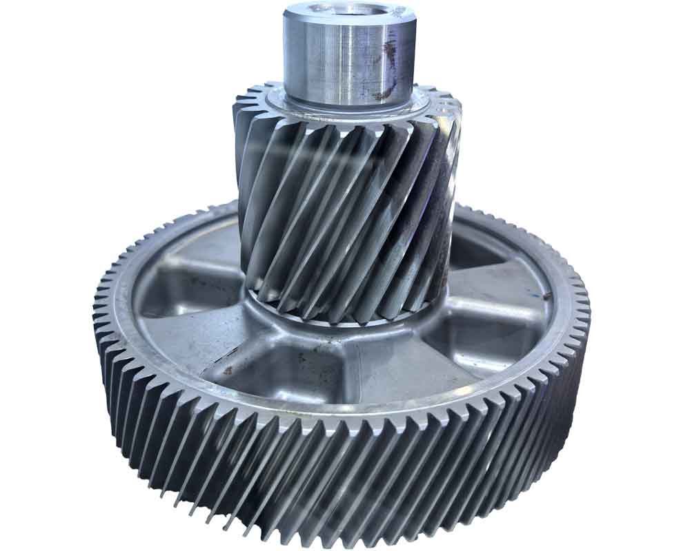
The system executed the virtual gear cutting process as per the described algorithm. The resulting three-dimensional solid model of the gear displayed all characteristic features of a correctly cut cyclo-palloid bevel gear: the epicycloidal lengthwise curvature, correct pressure angle profiles, and proper fillet geometry. A critical comparison was made between the simulated model and a physical workpiece machined on a Klingelnberg CNC铣齿机 using the identical set of parameters. The tooth form, lead (spiral angle), and surface topography from the simulation showed exact correspondence with the physically cut gear teeth. This successful verification confirms that the simulation algorithm accurately mirrors the real-world gear cutting kinematics and material removal process, establishing it as a reliable tool for pre-production validation.
Discussion on System Utility and Applications
The developed gear cutting simulation system transcends simple visualization. It serves as a virtual prototyping and diagnostic platform with significant engineering applications:
- Design Parameter Validation: Before committing to costly physical trials, engineers can test different gear design modifications (e.g., pressure angle, spiral angle) and immediately observe their impact on the tooth form, checking for potential undercut or pointed teeth.
- Machine Setting Optimization: The system allows for the safe exploration of machine setting adjustments. The effect of changes to the basic machine settings (like cutter tilt or modifying roll motions) on the tooth contact pattern and root geometry can be studied virtually.
- Generation of High-Fidelity CAD Models: The resulting solid model is geometrically precise and can be exported for use in Finite Element Analysis (FEA) for stress and contact analysis, or for creating CAD models of mating assemblies.
- CNC Code Verification: For advanced applications, the underlying kinematic model of the simulation can be used to verify or even post-process CNC programs for 5-axis gear cutting machines, ensuring the toolpath will produce the desired geometry.
- Training and Education: The system provides an excellent tool for understanding the complex principles behind the gear cutting process for cyclo-palloid gears without requiring access to actual production machinery.
Future enhancements could include the simulation of surface roughness based on feed rates, thermal effects, and the integration of advanced collision detection between the cutter body (not just the generating tooth) and the gear blank or machine components.
Conclusion
This research has successfully detailed the development and implementation of a dedicated gear cutting simulation system for Klingelnberg-type cyclo-palloid bevel gears. By leveraging the fundamental principles of the planar generating gear method and emulating the multi-axis kinematics of modern CNC gear cutting machines through discrete Boolean operations, the system achieves a high-fidelity virtual manufacturing environment. The core algorithm, which involves the iterative intersection and accumulation of material removal volumes, has proven effective in generating accurate 3D solid models of the gears. The verification through a direct comparison with a physically manufactured part confirms the system’s reliability. This simulation tool is therefore of significant practical importance. It provides gear engineers with a powerful means to verify and optimize both design and machine setting parameters prior to actual gear cutting, reducing development time, cost, and risk of manufacturing errors, while also supplying precise digital models for subsequent engineering analyses.