The principle of machining variable hyperbolic arc gear with rotating cutter head is shown in Figure 1. With double-edged cutting, the workpiece rotates around its own axis oz on the one hand, and moves back and forth along the horizontal direction ox on the other hand, forming a close generative motion with the cutter; when machining, the cutter cuts out the concave and convex surface of the tooth surface at the same time, and after machining a pair of tooth surfaces, it needs to be graded, and then the next pair of tooth surfaces is machined until the whole gear is machined.
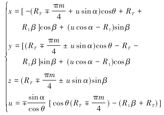
According to the machining method, the tooth surface equation is deduced as follows

Where, u is the displacement of any point on the tool surface from the cutting edge to the reference point; α is the pressure angle corresponding to the inner and outer cutting edges of the tool; RT is the radius of the nominal rotating cutter head; R1 is the radius of the gear blank indexing circle; m Is the gear module; β is the angle of the cutter from the middle section of the gear blank to the end face in the machining process; θ is the angle of the gear turning, RAD; “±” is used to indicate the concave and convex surface of the gear, and the upper symbol is used for the convex surface.
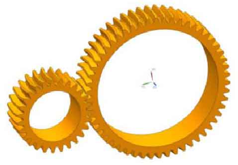
By substituting the gear geometric parameters into the equation and setting the value range and value of the tooth surface parameters β and θ, the discrete point cloud of the tooth surface can be obtained through numerical calculation; by importing the point cloud into the 3D modeling software for surface reconstruction, the digital tooth surface can be obtained; by stitching the surface, a single tooth can be obtained, and then the 3D solid model of the gear can be obtained through array operation. The geometric model of the variable hyperbolic arc gear pair constructed by the digital modeling method is shown in Figure 2.


