

According to the actual meshing process of gear pair, the interface of a pair of gear pairs is filled with lubricating oil medium when the gear box is meshing and driving, so as to play a lubricating role in the gear pair and reduce the rapid wear between the gear pairs, resulting in the rapid damage of the gear pair. Although the effect of lubricating oil can reduce the friction effect between gear pairs, there is still a small friction effect between tooth surfaces, so as to further study the characteristics of gear time-varying meshing stiffness under friction coefficient.

The crack initiation diagram of gear tooth surface listed in Fig. 1 shows that the friction direction of the gear surface changes along the tooth profile, mainly taking the pitch line as the boundary, the pure rolling motion without friction occurs between the two gears at the pitch line meshing position, while the rolling sliding phenomenon occurs at the pitch line to the tooth root or pitch line to the tooth top position, and the friction direction is opposite, so the gear tooth under this condition is subject to simple load See Figure 2 for the schematic diagram.
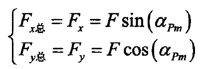
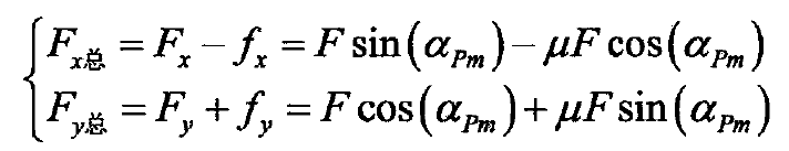
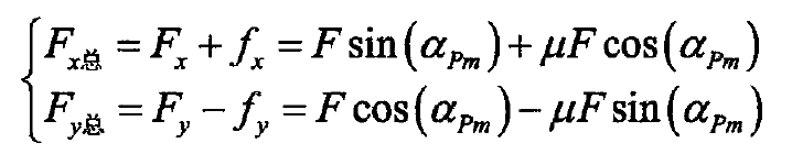
According to the loading conditions of gear teeth under three kinds of loads and friction as shown in Fig. 2, the total load component formula of load and friction along x-axis and y-axis in the three kinds of conditions can be expressed as follows:
1) The meshing point is at the pitch line position without friction (Fig. 2 (a));
2) The meshing point is from the pitch line to the tooth root, and there is friction (Fig. 2 (b)):
3) The meshing point is located between the pitch line and the tooth tip, and there is friction (Fig. 2 (c));
Because the contact stiffness and the gear matrix stiffness are related to the normal load of the load, and the normal load is not affected by friction, the stiffness calculation formula of the two is still based on the derived stiffness equation. By substituting the formula into the calculation equation of gear tooth stiffness by energy method, the general expressions of compression stiffness Ka, shear stiffness KT and bending stiffness KB of each component of gear tooth stiffness can be derived as shown in the formula, and the corresponding values of μ FX and μ FY according to the different positions of meshing points are shown in the formula.

