The basic idea of using finite element method to calculate the time-varying meshing stiffness of gear pair is to discretize the gear body and gear teeth into elastic micro elements, and deduce the time-varying meshing stiffness of gear pair through the elastic deformation response of relevant mechanical theory under external load. This method can be adopted by researchers to simulate the real geometry and boundary conditions of detailed gear physical model Use. At the same time, it can be used to verify the validity and accuracy of the proposed analytical model and results.
The simulation parameters of gear pair 1 are selected and the finite element method is used to simulate the time-varying meshing stiffness. In order to ensure the authenticity of the finite element calculation model, the corresponding two-dimensional plane geometry is established according to the derived tooth profile subsection equation (fillet curve AB and involute curve BD), and then the corresponding three-dimensional mathematical model is constructed in the three-dimensional modeling software according to the two-dimensional geometry Finally, the model is discretized to form a finite element simulation model. The brief modeling process is shown in Figure 1. In order to improve the reliability of the simulation results, a relatively regular hexahedral shape element is used in the discretization of the finite element model, and the local mesh of the two meshing gears is refined at the same time. On the one hand, the nodes can be captured On the other hand, it can shorten the simulation time and improve the calculation efficiency. The specific three-dimensional finite element discrete model and local refined mesh of gear teeth are shown in Figure 2.
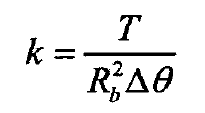
Figure 3 shows the schematic diagram of the boundary conditions set for the finite element simulation calculation. The boundary conditions are set as follows: the inner hole of the driven gear applies fixed constraints, while the inner hole of the driving gear applies torque, and the load transfer function of the gear teeth is simulated by creating contact between the meshing surfaces of the gear teeth. Finally, the rotation angle of the driving gear is extracted, and the torsional stiffness is converted into linear stiffness according to the formula The method is used to convert the stiffness values.

Where:
T-gear action torque, nm;
Δ θ – deformation angle of loaded gear, RAD;
RB – radius of gear base circle, m;


