
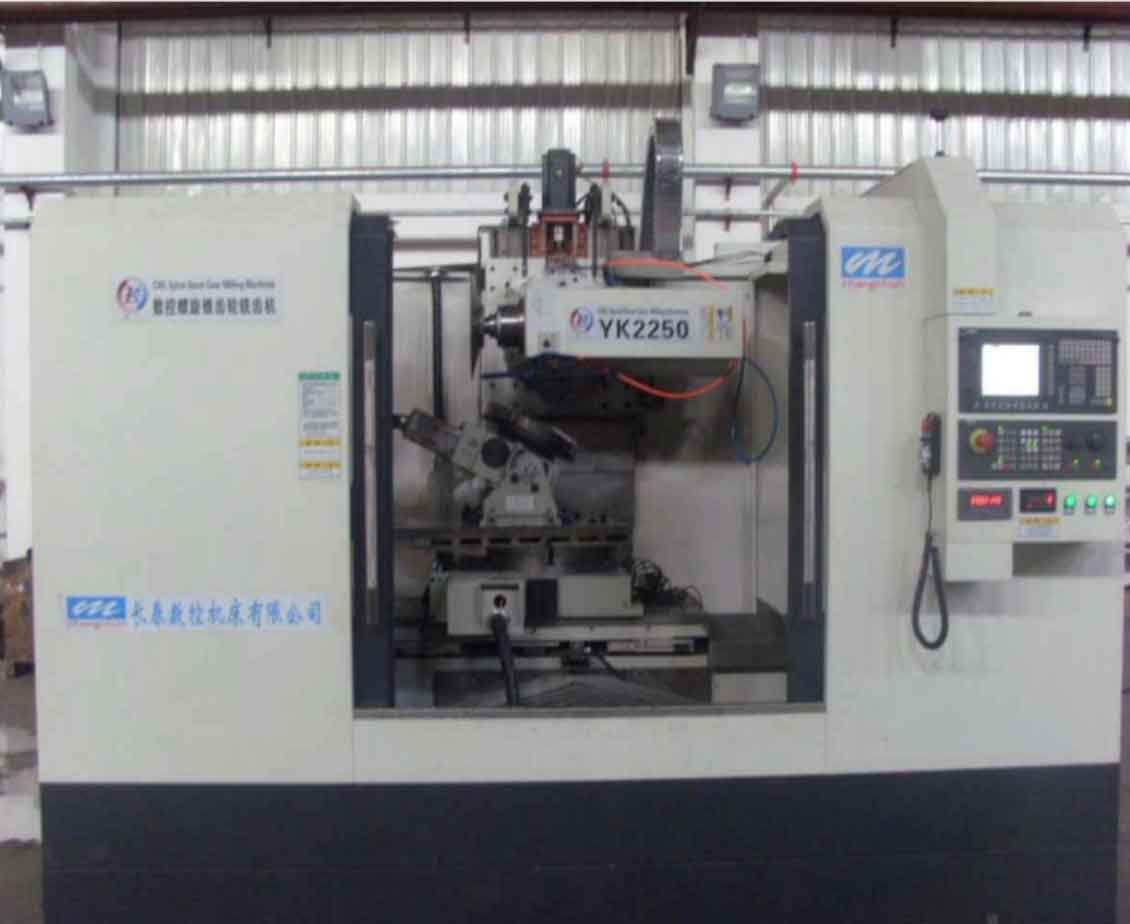
In my extensive involvement with gear milling technologies, I have encountered various machines designed for bevel gear production, but the double-head straight bevel gear milling machine stands out for its efficiency and precision. This machine is specifically engineered for machining straight bevel gears, making it highly suitable for industries such as automotive and tractor manufacturing. Its advantages become particularly evident in medium to large batch production, where it demonstrates remarkable productivity. The machine supports multi-unit management and paired gear production, allowing for flexible roughing and finishing operations. Gear milling is at the core of its functionality, enabling high-speed processing with consistent quality.
The primary technical specifications of this gear milling machine are summarized in the table below. These parameters define its capacity and ensure it meets the demands of industrial applications.
| Parameter | Value |
|---|---|
| Workpiece Module | 2.5–8 mm |
| Workpiece Diameter | Up to 300 mm |
| Workpiece Pitch Cone Angle | 0°–90° |
| Maximum Tooth Face Width | 60 mm |
| Vertical Movement of Workpiece Slide | 150 mm |
| Maximum Number of Teeth for Automatic Indexing | 120 |
| Gear Accuracy Grade | Class 8 (per relevant standards) |
| Tooth Surface Finish | Ra 3.2 µm or better |
The cutting principle of this gear milling machine is based on the planar gear theory, utilizing the generating method, also known as the roll-cutting or enveloping method. In gear milling, two circular milling cutter heads, each equipped with 10 inserted cutter teeth and with a diameter of 600 mm, are employed. The cutter teeth are positioned alternately and set at a specific angle corresponding to the tooth space angle of the gear being machined. These cutter heads are placed in the position of a imaginary generating plane gear. To achieve the generating motion required for tooth profile machining, the machine ensures a pure rolling motion without backlash between the workpiece (the gear being cut) and the imaginary generating plane gear represented by the cutter heads. This is accomplished through a planetary motion involving rotation and revolution of the workpiece head relative to the cradle. The pitch cone surface of the workpiece rolls purely on the pitch plane of the generating plane gear, while the cutter heads simply rotate at fixed positions. For each rolling cycle, the cutter heads mill one tooth space. A retraction mechanism withdraws the cutter heads from the cutting plane (the generating plane), and an indexing mechanism completes the division for the workpiece, allowing continuous processing of the entire gear ring.
The mathematical representation of this gear milling process can be expressed using the following relationships. Let $\alpha$ be the pressure angle, $\delta$ be the pitch cone angle, and $\delta_f$ be the root cone angle of the gear. For a paired gear set, the average root cone angle is given by $\delta_{f,avg} = (\delta_{f1} + \delta_{f2})/2$, where $\delta_{f1}$ and $\delta_{f2}$ are the root cone angles of the two gears. During gear milling, the cutter heads simulate the teeth of the generating plane gear, and the relative motion ensures accurate tooth formation.
The machine features an indeterminate geometric center modular design, which allows for adjustable geometric centers during gear milling to accommodate various gear specifications. This flexibility contributes to its ease of operation, reliable performance, and high productivity. In fact, the efficiency of this gear milling machine is approximately 4 to 6 times that of traditional bevel gear planers. The hydraulic system is well-developed, with an operational valve coordinating the actions of various cylinders, ensuring logical execution of mechanical movements and interlocking functions. The sequence of operations is critical: during rolling, the cradle moves first, followed by the cutter heads advancing to the generating plane gear position to initiate the generating motion for a tooth space; during retraction, the cutter heads withdraw first, then the cradle rolls back. A damping device in the system minimizes vibrations during gear milling.
One of the key advantages in gear milling with this machine is its ability to produce crowned teeth. The two large circular cutter heads have cutter teeth with cutting edges inclined at an angle $\beta$, which facilitates the machining of crowned teeth, thereby enhancing gear service life. Since both gears in a pair are cut by the same set of cutter heads (representing the generating plane gear), they achieve proper meshing. The dual-workstation design allows for cutting from opposite directions, optimizing tool usage and extending tool life. The indexing mechanism is simple, using only one set of change gears to handle the indexing tasks within the machine’s specified range.
The generating motion chain involves two worm gear pairs: one for the cradle (using a tapered thread worm) and one for the indexing head (using a two-piece combined worm wheel with disc springs for automatic backlash elimination). This design simplifies assembly and adjustment, ensuring precision in the generating chain during gear milling.
Crowned teeth, or鼓形齿, are formed during gear milling by inclining the main cutting edges of the cutter teeth relative to the cutter axis. This inclination angle $\beta$ creates a concave conical surface on the imaginary generating plane gear, resulting in a convex tooth profile on the workpiece. The crown amount $\Delta h$ is a measure of the tooth profile convexity, defined as the distance from the tooth ends to the midpoint along the tooth length. The calculation of crown amount involves geometric relationships based on cutter parameters and gear dimensions.
Let $L$ be the tooth length (face width) of the gear, $D_c$ be the cutter head diameter, and $\beta$ be the inclination angle. The maximum concave depth $\Delta e$ at the tooth root can be derived as:
$$\Delta e = \frac{L^2}{8D_c}$$
However, for crowned teeth, the crown amount $\Delta h$ is more relevant. It is given by:
$$\Delta h = \frac{L^2 \tan \beta}{4D_c \cos \alpha}$$
where $\alpha$ is the pressure angle. This formula shows that $\Delta h$ is proportional to $L^2$ and $\tan \beta$, and inversely proportional to $D_c$ and $\cos \alpha$. In this gear milling machine, the cutter head diameter is fixed at 600 mm, so for a given pressure angle (e.g., 20°), different tooth lengths yield different crown amounts, as summarized in the table below.
| Tooth Face Width L (mm) | Crown Amount Δh (mm) |
|---|---|
| 20 | 0.01 |
| 30 | 0.022 |
| 40 | 0.04 |
| 50 | 0.062 |
| 60 | 0.09 |
Crowned teeth offer several benefits in gear milling applications: they improve the contact pattern of straight bevel gear pairs, avoiding edge contact and its associated damage; reduce sensitivity to assembly errors; and minimize the effects of load-induced changes during meshing. Overall, crowned teeth enhance the durability and expand the applicability of straight bevel gears, making gear milling with this machine particularly valuable for high-performance requirements.
The selection of change gears for feed speed, indexing, and rolling is crucial in gear milling operations. Feed speeds are adjusted via a three-speed feed box and a two-stage V-belt drive, offering six feed rates. The unique feature is that the return speed equals 1.5 or 2 times the rolling speed, depending on the setting. The feed speed table is as follows:
| Feed Box Level | Belt Drive Level | Feed Speed (degrees/second, including return) |
|---|---|---|
| I | Low | 0.5 |
| I | High | 1.0 |
| II | Low | 1.5 |
| II | High | 2.0 |
| III | Low | 3.0 |
| III | High | 4.0 |
The choice of feed speed depends on the module of the gear and whether roughing or finishing is being performed. Cutting speeds are adjusted via a two-stage V-belt on the cutter head drive motor, offering two options: 50 m/min or 80 m/min, which are essential for efficient gear milling.
For indexing gear selection, the principle is similar to other single-index bevel gear machines. The indexing is achieved by the generating motion between the workpiece and cutter heads. After milling one tooth space, the cutter heads retract, and during the return motion, an indexing mechanism ensures the workpiece rotates by one additional tooth. The indexing formula is:
$$i = \frac{K}{z} = \frac{A}{B} \cdot \frac{C}{D}$$
where $i$ is the indexing ratio, $K$ is a machine constant (specific to the indexing head), $z$ is the number of teeth on the workpiece, and $A$, $B$, $C$, $D$ are the change gears. The machine offers four types of indexing heads, selected based on the workpiece mounting angle, number of teeth, and module. The change gear $C$ is chosen according to the indexing head type, as shown in the table below.
| Indexing Head Type | Workpiece Mounting Angle (degrees) | Workpiece Tooth Count Range | Change Gear C Teeth | Worm Gear Ratio |
|---|---|---|---|---|
| Type I | 0–30 | 10–120 | 24, 28, 32, 36, 40 | 1:60 |
| Type II | 30–60 | 10–100 | 24, 28, 32, 36 | 1:90 |
| Type III | 60–90 | 10–80 | 20, 24, 28, 32 | 1:120 |
| Type IV | All | Even teeth only | 24, 28, 32 | 1:180 |
In cases where change gears are insufficient, the gear $C$ can be selected as an integer multiple of the workpiece tooth count to compensate, ensuring precise indexing in gear milling.
The rolling change gears determine the generating motion between the workpiece and the imaginary generating plane gear. If the imaginary generating plane gear has $z_c$ teeth (where $z_c = \infty$ for a plane gear), and the workpiece has $z$ teeth, then when the imaginary gear rotates one revolution, the workpiece rotates $z_c / z$ revolutions. The rolling ratio is given by:
$$i_r = \frac{z_c}{z} = \frac{N}{z}$$
where $N$ is the cradle worm wheel tooth count, a machine constant. For orthogonal gears with shaft angle $\Sigma = 90^\circ$, the rolling change gears are set as:
$$i_r = \frac{\tan \delta}{z}$$
where $\delta$ is the pitch cone angle. For non-orthogonal gears with $\Sigma \neq 90^\circ$, the formula adjusts based on trigonometric relationships. This ensures accurate generating motion during gear milling.
The gear milling machine incorporates a compact gear swing block indexing mechanism. This mechanism uses a swing block that engages with forward and reverse stops to achieve intermittent indexing. During rolling, the forward stop contacts the swing block; during return, the reverse stop engages, causing the indexing worm wheel to rotate by a fraction of a revolution. After the cycle, the workpiece has effectively rotated by one tooth. This design simplifies the indexing process and enhances reliability in gear milling operations.
The circular cutter heads are equipped with 10 inserted cutter teeth each, arranged alternately and symmetrically about the cradle centerline at an angle of $\theta$ (equal to the tooth space angle). The cutter teeth are critical components in gear milling, and their geometry must be precisely controlled. Key parameters include the tooth profile angle, relief angles, and dimensions. The cutter tooth is essentially a form tool, with its cutting edge inclined at angle $\beta$ relative to the cutter axis to facilitate crowned tooth machining.
The manufacturing angle $\gamma_0$ for the cutter teeth is calculated based on the inclination angle $\beta$ and the pressure angle $\alpha$. From spatial geometry, the relationship is:
$$\tan \gamma_0 = \tan \beta \cdot \sin \alpha$$
where $\gamma_0$ is the side rake angle in the tool’s coordinate system. The cutter tooth profile angle $\alpha_c$ on the cutter head is derived from the gear pressure angle and the relief angles. If $\alpha_c$ is the cutter tooth profile angle, and $\alpha$ is the gear pressure angle, then for a relief angle $\lambda$, the error in $\alpha_c$ due to manufacturing tolerances can be expressed as:
$$\Delta \alpha_c = \frac{\Delta \lambda}{\cos^2 \alpha_c}$$
This highlights the need for precision in cutter tooth fabrication to maintain accuracy in gear milling.
The width $b$ of the cutter teeth is determined based on the gear tooth space dimensions. It must satisfy:
$$b \geq \frac{w_{max} + w_{min}}{2} + s$$
where $w_{max}$ and $w_{min}$ are the maximum and minimum widths of the gear tooth space at the root, and $s$ is a clearance (typically 0.1–0.2 mm). The gear tooth space widths can be calculated from gear geometry. For a straight bevel gear, the tooth space width at the root varies linearly along the tooth length. If the design does not meet this criterion, adjustments such as roughing and finishing, reducing face width, or modifying gear design may be necessary in gear milling.
Manufacturing the cutter teeth requires high-precision fixtures due to the need for consistency among the 10 teeth per cutter head. Key fixtures include those for milling the tooth profiles and for grinding relief angles. For example, a fixture for milling the tooth faces might process 5 teeth at once, while a grinding fixture handles 2 teeth per setup. These fixtures ensure that all cutter teeth have identical geometry, which is essential for achieving high-quality gear milling results. After fabrication, the cutter teeth are inspected, marked, and stored in sets.
Resharpening of cutter teeth after wear is performed on a dedicated sharpening machine or using fixtures on surface and cylindrical grinders. To facilitate machine adjustment after sharpening, the amount of material removed is recorded, as shown in the table below. In mass production, multiple sets of cutter heads can be rotated to minimize machine readjustments.
| Cutter Head Set | Initial Thickness (mm) | Material Removed After 1st Sharpening (mm) | Material Removed After 2nd Sharpening (mm) | Material Removed After 3rd Sharpening (mm) |
|---|---|---|---|---|
| Set 1 | 10.00 | 0.10 | 0.15 | 0.20 |
| Set 2 | 10.00 | 0.12 | 0.18 | 0.22 |
| Set 3 | 10.00 | 0.08 | 0.13 | 0.18 |
After each sharpening, adjustments for tooth depth $\Delta h’$ and tooth thickness $\Delta s’$ are calculated based on the removed material $\Delta b$. The relationships are:
$$\Delta h’ = \Delta b \cdot \tan \alpha$$
$$\Delta s’ = 2 \Delta b \cdot \tan \lambda$$
where $\lambda$ is the relief angle. These adjustments ensure that the gear milling process maintains consistent tooth dimensions.
In summary, this double-head straight bevel gear milling machine represents a significant advancement in gear milling technology. Its generating principle, modular design, and ability to produce crowned teeth make it highly efficient and versatile for industrial applications. The precise control over feed speeds, indexing, and rolling through change gears, coupled with robust cutter head design, ensures high accuracy and surface finish. However, it is worth noting that the indexing worm gear has a relatively low tooth count and uses disc springs for backlash elimination, which may increase wear over time. Additionally, the machine does not support hydraulic clamping of gear blanks, which could be a limitation in some setups. Despite these minor drawbacks, the machine’s productivity and flexibility make it a valuable asset for gear milling in high-volume production environments, consistently delivering quality gears for demanding applications.