
According to the characteristics of spur bevel gear parts and the requirements of closed cold precision forging process, the following problems must be considered in the design of forging drawing:
1). Selection of parting surface position
The choice of the position and shape of the parting surface determines the forging forming, die drawing, forging quality, material utilization and the complexity of the manufacturing of the forging die and trimming die.
In order to ensure that the forgings can be easily taken out from the die cavity of the forging die, the shape of the forgings shall be the same as that of the parts as far as possible, strive to obtain the best filling effect, and ensure the reliable production process and stable quality of the forgings, the position of the parting surface of the forgings shall be selected at the position with the largest horizontal projection size. In the selected closed precision forging process, the parting surface of the upper and lower female dies is the same as that of the open die forging of bevel gears. In the design of forging drawing, only the position of inner hole skin connection needs to be considered.
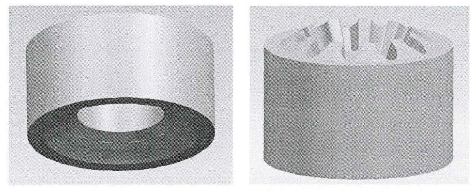
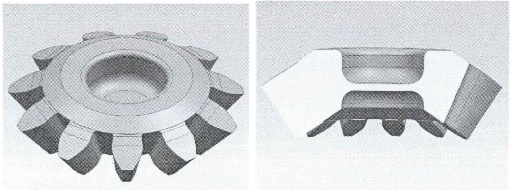
According to the parting principle, the parting surface is designed at the maximum diameter of the forging, and the tooth shape is completely forged in the lower die. Therefore, the design of the upper and lower dies for spur bevel gears is shown in Figure 1.
2). Die forging slope
In order to take the formed forgings out of the die, a certain additional slope or inherent slope is required on the plane or surface perpendicular to the parting surface on the forgings. Because the height dimension of the straight bevel gear is relatively small, the upper and lower holes of the punching connecting skin are shallow, and its die inclination has little impact on the machining workload. Therefore, in order to facilitate the smooth demoulding of the punch, the die inclination is selected as α= 0.5°, β = 1.0°。
3). Fillet radius
In order to make the metal flow easily, fill the cavity, improve the quality of forgings and prolong the service life of forging dies, all intersecting surfaces on die forgings must be designed with forging fillets.
The function of convex fillet (outer fillet) r is to avoid the cracking of the forging die due to stress concentration during heat treatment and die forging, so that the metal can fill the corresponding parts. The function of the four round corners (fillets) r is to make the metal easy to flow, prevent folding, and prevent premature wear and collapse of the die bore. In general, the value of convex fillet is r=1, while the value of concave fillet corresponds to the value of convex fillet, as shown in the following formula:
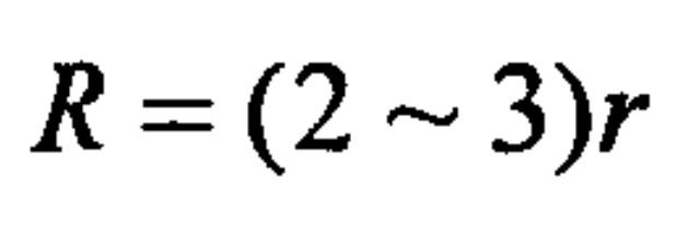
Take R=3.
4). punching recess
One of the key problems in the design of forging drawing is to set the punching connecting plate in the height direction. Its position not only directly affects the size of the upper and lower punches and the position of the end stroke in the structural design of the closed die, but also affects the material flow and the filling of forgings in the forming process. Take its position and thickness as the process factors affecting the filling forming to conduct simulation analysis to determine its optimal size. Before that, the following preliminary size design is carried out.
According to the size of the straight bevel gear, the diameter of the through hole of the part is 28mm. The form of flat bottom with skin is selected for design, and its thickness is calculated according to the following formula:
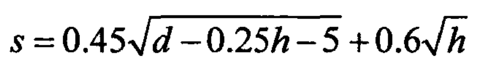
Where, D is the diameter of the inner hole of the forging; H is the height of the inner hole of the forging, and h=6mm, 8mm and 7.3mm are respectively selected for size design.
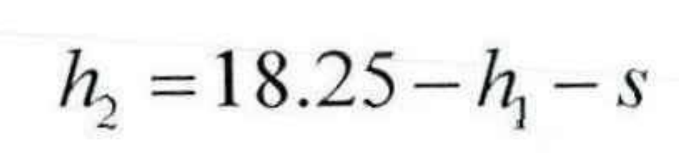
Height of blind hole of upper mold:
Height of blind hole of lower mold:
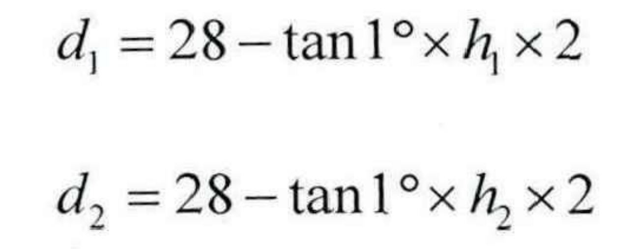
Bottom diameter of upper and lower die blind hole:
Select the initial upper die blind hole height h=6mm, 8mm, 7.3mm, and conduct numerical calculation according to the above formula to obtain three groups of forging data, as shown in the following table:
| Number | h1 | h2 | s | d1 | d2 |
| 1 | 6.00 | 8.70 | 3.56 | 27.79 | 27.70 |
| 2 | 8.00 | 6.50 | 3.76 | 27.72 | 27.77 |
| 3 | 7.30 | 7.26 | 3.70 | 27.75 | 27.75 |
According to the above design dimensions, the forging drawing design of the spur bevel gear is completed on, as shown in Figure 2.
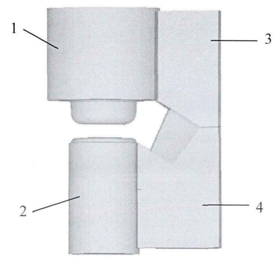
Fig. 3 is the die structure diagram for simulation analysis of closed precision forging process, in which the pressing position of the upper and lower punches is related to the position of punching connection.