
The in-depth study on the optimization design of mesh efficiency for hypoid gears in drive axles is conducted. The focus is on cycloid hypoid gears, which are widely used in commercial vehicle drive axles due to their short production cycle. The research aims to improve gear mesh efficiency, which is crucial for achieving energy conservation and emission reduction in the automotive industry. The following content summarizes the key findings and methodologies used in this research, with tables and images for better readability.
1. Introduction
Cycloid hypoid gears are characterized by their continuous indexing processing, leading to efficient production. They have been widely adopted in commercial vehicle drive axles. However, the performance of these gears, such as mesh efficiency, loaded transmission error, contact stress, and contact pattern, is significantly influenced by tooth surface modification. This research aims to optimize the tooth surface design of cycloid hypoid gears to maximize mesh efficiency under driving conditions.
2. Methodology
2.1 Tooth Surface Design Method
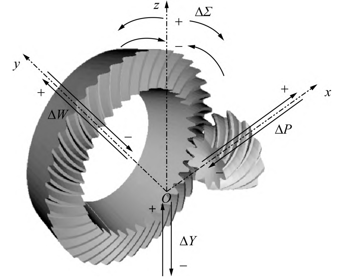
The tooth surface design of cycloid hypoid gears requires consideration of both sides of the tooth surface due to their simultaneous engagement. Additionally, the deformation of the transmission system during operation can lead to mesh misalignment, which affects gear contact performance. Therefore, the design process takes into account the effect of mesh misalignment.
The tooth surface design is achieved by presetting the peak-to-peak value of the no-load transmission error and the no-load contact pattern. The design variables include the slope of the preset contact line, the semi-major axis of the preset contact ellipse, and the preset transmission error peak-to-peak value for both the drive and coast sides.
| Design Variables | Description | Symbol |
|---|---|---|
| Slope of preset contact line (drive side) | Controls the inclination of the contact line | kc |
| Semi-major axis of preset contact ellipse (drive side) | Controls the size of the contact area | bc |
| Preset transmission error peak-to-peak value (drive side) | Controls the transmission error | PTE,c |
| Slope of preset contact line (coast side) | Controls the inclination of the contact line | kv |
| Semi-major axis of preset contact ellipse (coast side) | Controls the size of the contact area | bv |
| Preset transmission error peak-to-peak value (coast side) | Controls the transmission error | PTE,v |
2.2 Gear Friction Loaded Contact Analysis Method (FLTCA)
The FLTCA method is used to analyze the contact performance indicators, including mesh efficiency, loaded transmission error, contact stress, and contact pattern. The main steps of the FLTCA method are as follows:
- Determine input parameters: Gear geometry, operating conditions, and lubrication parameters.
- Calculate actual tooth surfaces: Simulate the actual machining process.
- Perform no-load contact analysis (TCA): Calculate the contact points under ideal conditions.
- Loaded contact analysis: Consider deformation and friction to calculate the loaded contact performance.
2.3 Optimization Model
The optimization objective is to maximize the mesh efficiency (η) under driving conditions. The constraints include controlling the loaded transmission error (LTE), contact stress (CP), and avoiding edge contact.
| Objective and Constraints | Formula | Description |
|---|---|---|
| Objective | Maximize η | Maximize mesh efficiency |
| LTE Constraint | LTE≤LTE0 | Control loaded transmission error |
| CP Constraint (drive side) | CPc≤CPc0 | Control contact stress on drive side |
| CP Constraint (coast side) | CPv≤CPv0 | Control contact stress on coast side |
| Edge Contact Constraint (drive side) | ΔSc≤ΔSc0 | Avoid edge contact on drive side |
| Edge Contact Constraint (coast side) | ΔSv≤ΔSv0 | Avoid edge contact on coast side |
2.4 Solution Method
To reduce the computational time and improve efficiency, a Kriging surrogate model combined with a Multi-Island Genetic Algorithm (MIGA) is used to solve the optimization problem.
3. Experimental Validation
3.1 Test Setup
The optimized gear design is validated through experiments on a drive axle system loading test bench. The test setup includes the drive axle fixed on a support, with the input axle connected to a dynamometer for measuring input power and the semi-axes connected to dynamometers for measuring load power.
3.2 Test Results
Comparisons are made between the optimized gear design and the original design. The results show that the power loss of the optimized design is reduced, and the system efficiency is improved. Specifically, at the cruise condition of 80 kW load power and 80 km/h speed, the power loss is reduced by about 300 W, and the system efficiency is increased by about 0.4%.
| Test Conditions | Original Design | Optimized Design | Improvement |
|---|---|---|---|
| Load Power (kW) | 80 | 80 | – |
| Speed (km/h) | 80 | 80 | – |
| Power Loss (W) | Higher value | 300 W less | -300 W |
| System Efficiency (%) | Lower value | Increased by 0.4% | +0.4% |
4. Conclusion
This research presents an optimization design method for the tooth surface of cycloid hypoid gears, aiming to maximize mesh efficiency under driving conditions. By considering factors such as mesh misalignment, loaded transmission error, contact stress, and contact pattern, an optimization model is established. The model is solved using a Kriging surrogate model combined with a Multi-Island Genetic Algorithm. Experimental results validate the effectiveness of the proposed method, demonstrating reduced power loss and improved system efficiency.