
I propose an efficient method for milling and grinding straight bevel gears by using a pair of dual interlocking circular cutters. The method is intended to overcome the limitations of conventional straight bevel gear manufacturing, such as low modification accuracy, insufficient productivity, and difficulty in achieving high-performance tooth surfaces. In this approach, two cutter disks simultaneously cut both sides of a tooth space. By controlling the relative position between the cutters and the workpiece, the tooth can be completed without any feed motion along the tooth width. This simplifies the machine tool structure, shortens the machining time, and improves productivity. The resulting straight bevel gear pair is analyzed through tooth contact analysis (TCA) and loaded tooth contact analysis (LTCA). Tool parameters, including the profile modification coefficient, the average cutter disk radius, and the cutting edge angle, are introduced to establish a tooth surface model that considers both profile modification and lengthwise modification. On this basis, I optimize the cutter parameters with a genetic algorithm to minimize the loaded transmission error fluctuation. The optimized straight bevel gear pair shows a significant reduction in vibration excitation under working load.
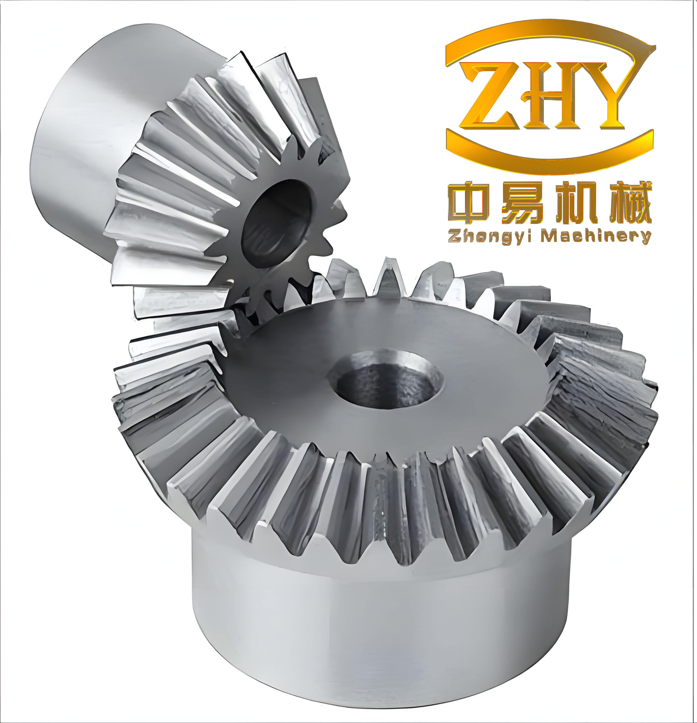
Straight bevel gears are widely used in intersecting-axis motion and power transmission. They have a simple structure, small axial force, and convenient installation. They are common in aerospace, automotive, and industrial applications. With the rapid development of electric vehicles, traditional design and manufacturing methods for straight bevel gears can no longer satisfy the requirements of high strength, low noise, and high reliability for drive axle differentials. Precision-forged straight bevel gears usually have low accuracy and cannot be designed with tooth surface modification. Planing processes offer limited adjustment freedom, and tooth surface modification is difficult to realize. Therefore, it is necessary to explore new methods for manufacturing high-performance straight bevel gears.
In recent years, dual interlocking disk cutters have been used on six-axis CNC gear milling machines to improve the machining accuracy and efficiency of straight bevel gears and to enhance contact performance. Mathematical models of dual interlocking disk cutters have been established, and the influence of cutter parameters on the tooth surface contact pattern has been studied. Some researchers have simulated crown generating wheels to machine straight bevel gears and performed virtual machining on six-axis CNC gear milling machines. Others have investigated the mathematical model of face hobbing for straight bevel gears. Concave cutter disks have been used to machine straight bevel gears and to perform tooth contact analysis. Equivalent conversion between a dual-cutter-disk gear milling machine and a Free-form machine has been established, and cutting and rolling tests of straight bevel gears have been carried out. To improve transmission performance and reliability, anti-wear design and analysis methods for straight bevel gear tooth surfaces have been proposed. Generation methods for the tooth surface and root transition surface of straight bevel gears have been used to analyze root bending stress. Low-sensitivity design and analysis of modified straight bevel gears have been studied, and rolling tests have been conducted. Tooth contact analysis and transmission error calculation based on measured tooth surfaces have also been reported. Crowning of straight bevel gear tooth surfaces has been designed, and a method for calculating the crowning vertex position and modification amount has been proposed to make the load distribution more uniform. A tooth contact analysis method based on the golden ratio method has been presented. Different modification methods for forged straight bevel gears have been discussed, and their influence on transmission error has been analyzed to find the best modification approach.
To overcome the shortcomings of low modification accuracy, low efficiency, and difficulty in achieving high-performance tooth surface machining for straight bevel gears, I propose an efficient dual interlocking circular cutter milling and grinding method. The method uses two cutter disks to cut both sides of the gear tooth simultaneously. By controlling the relative position between the cutter and the workpiece, the tooth can be machined without feed motion along the tooth width. This simplifies the machine tool structure, shortens the machining time, and improves machining efficiency. I establish a tooth contact analysis model and a loaded tooth contact analysis model for the straight bevel gear pair. I analyze the influence of cutter parameters on meshing performance. On this basis, I use a genetic algorithm to optimize the cutter parameters with the minimum loaded transmission error fluctuation as the objective. The optimized straight bevel gear pair is expected to provide a new way for the design and manufacture of high-performance straight bevel gears.
1. Principle of Dual Interlocking Circular Cutter Machining
I use identical dual interlocking circular cutters to machine the pinion and the gear. The resulting gear pair is fully conjugate. Under assembly errors, edge contact may occur, causing vibration and noise. To avoid this, I introduce tool profile modification. The tool normal section reference coordinate system is denoted as \(S_m\), and the tool moving coordinate system is denoted as \(S_n\). The position vector of a cutting point \(Q\) can be expressed as
$$ \mathbf{r}_m^{(Q)}(u) = \begin{bmatrix} 0 \\ u_0 + u \\ a_t (u_0 + u)^2 \\ 1 \end{bmatrix} $$
where \(u\) is the position vector from \(O_m\) to an arbitrary point on the cutting edge, \(u_0\) is the origin position of the parabolic modification curve, and \(a_t\) is the parabolic modification coefficient of the tool profile. When \(a_t = 0\), the cutter is unmodified and generates a spatial involute tooth profile. The vector \(\mathbf{r}_m^{(Q)}(u)\) in \(S_m\) is transformed into the cutter disk coordinate system \(S_{cd}\), giving the position vector
$$ \mathbf{r}_{cd}(u,\phi) = \mathbf{M}_{cd,n}(\phi) \mathbf{M}_{n,m} \mathbf{r}_m(u) $$
The dual interlocking circular cutter simulates a crown generating wheel. The cutter actually consists of a pair of circular grinding wheels or milling cutter disks. The cutter rotates about its axis to form the generating tooth. In the crown generating wheel coordinate system \(S_{cg}\), the position vector of the cutter disk center is \(\mathbf{r}_{Ocd}\). The cutter disk reference coordinate system \(S_{cd}\) is established, where \(z_{cd}\) is the cutter disk rotation axis and \(y_{cd}\) points to the midpoint of the tooth width of the crown generating wheel. The homogeneous transformation matrix \(\mathbf{M}_{cg,cd}\) from \(S_{cd}\) to \(S_{cg}\) is
$$ \mathbf{M}_{cg,cd} = \begin{bmatrix} \mathbf{x}_{cd} \cdot \mathbf{x} & \mathbf{x}_{cd} \cdot \mathbf{y} & \mathbf{x}_{cd} \cdot \mathbf{z} & \mathbf{r}_{Ocd} \cdot \mathbf{x} \\ \mathbf{y}_{cd} \cdot \mathbf{x} & \mathbf{y}_{cd} \cdot \mathbf{y} & \mathbf{y}_{cd} \cdot \mathbf{z} & \mathbf{r}_{Ocd} \cdot \mathbf{y} \\ \mathbf{z}_{cd} \cdot \mathbf{x} & \mathbf{z}_{cd} \cdot \mathbf{y} & \mathbf{z}_{cd} \cdot \mathbf{z} & \mathbf{r}_{Ocd} \cdot \mathbf{z} \\ 0 & 0 & 0 & 1 \end{bmatrix} $$
where the vectors \(\mathbf{x} = [1, 0, 0]\), \(\mathbf{y} = [0, 1, 0]\), and \(\mathbf{z} = [0, 0, 1]\) are the three coordinate components of \(S_{cg}\). The normal section of the straight-line-edge dual interlocking circular cutter consists of a straight cutting edge and a tip arc with radius \(\rho_f\). An auxiliary vector \(\mathbf{t}_{aux}\) is defined as perpendicular to the plane formed by the unit normal vector \(\mathbf{n}_{cg}\) and the unit tangent vector \(\mathbf{t}_{\phi s}\), that is, \(\mathbf{t}_{aux} = \mathbf{n}_{cg} \times \mathbf{t}_{\phi s}\). Then the vector \(\mathbf{t}_{\phi s}\) is rotated about the auxiliary vector \(\mathbf{t}_{aux}\) by an angle \(\delta\), which is called the cutting edge angle. By changing the cutting edge angle \(\delta\), lengthwise modification of the tooth surface is realized, so that the cutter disk forms a cutting cone when cutting the gear.
The position vector of the crown generating wheel formed by the dual interlocking circular cutter is obtained by transforming from \(S_{cd}\) to \(S_{cg}\):
$$ \mathbf{r}_{cg}(u,\phi) = \mathbf{M}_{cg,cd} \mathbf{r}_{cd}(u,\phi) $$
The crown generating wheel generates the straight bevel gear. The coordinate systems \(S_{cg}\) and \(S_i\) are the moving coordinate system of the crown generating wheel and the moving coordinate system of the machined bevel gear, respectively. The subscript \(i = 1\) denotes the pinion, and \(i = 2\) denotes the gear. The coordinate systems \(S_j\), \(S_k\), and \(S_l\) are auxiliary coordinate systems, and \(\gamma_i\) is the pitch cone angle of the machined gear. The tooth surface of the straight bevel gear is the envelope of the family of crown generating wheel tooth surfaces. The position vector of the pinion or gear is
$$ \mathbf{r}_i(u,\phi,\psi_i) = \mathbf{M}_{il}(\psi_i) \mathbf{M}_{lk} \mathbf{M}_{kj} \mathbf{M}_{jcg} \mathbf{r}_{cg}(u,\phi) $$
The meshing equation is
$$ f_i^{cg}(u,\phi,\psi_i) = \left( \frac{\partial \mathbf{r}_i}{\partial u} \times \frac{\partial \mathbf{r}_i}{\partial \phi} \right) \cdot \frac{\partial \mathbf{r}_i}{\partial \psi_i} = 0 $$
Combining the above equations, the tooth surface equation of the straight bevel gear is obtained. The unit normal vector of the machined gear tooth surface is
$$ \mathbf{n}_i(u,\phi,\psi_i) = \frac{ \frac{\partial \mathbf{r}_i}{\partial u} \times \frac{\partial \mathbf{r}_i}{\partial \phi} }{ \left| \frac{\partial \mathbf{r}_i}{\partial u} \times \frac{\partial \mathbf{r}_i}{\partial \phi} \right| } $$
2. TCA and LTCA Models
2.1 Tooth Contact Analysis Model
In the TCA model, the coordinate systems of the pinion and the gear are \(S_1\) and \(S_2\), respectively. The fixed coordinate system is \(S_h\). The pinion meshing angle and the gear meshing angle are \(\varphi_1\) and \(\varphi_2\), respectively. In the fixed meshing coordinate system \(S_h\), the position vectors of the pinion and gear tooth surfaces are \(\mathbf{r}_h^{(1)}\) and \(\mathbf{r}_h^{(2)}\), and the unit normal vectors are \(\mathbf{n}_h^{(1)}\) and \(\mathbf{n}_h^{(2)}\). According to the continuous tangency condition of two meshing gears, the basic TCA equations for the straight bevel gear are
$$ \begin{cases} \mathbf{r}_h^{(1)}(u_1,\phi_1,\psi_1,\varphi_1) = \mathbf{r}_h^{(2)}(u_2,\phi_2,\psi_2,\varphi_2) \\ \mathbf{n}_h^{(1)}(u_1,\phi_1,\psi_1,\varphi_1) = \mathbf{n}_h^{(2)}(u_2,\phi_2,\psi_2,\varphi_2) \end{cases} $$
The TCA equations contain seven equations and eight unknowns: \(u_1, \phi_1, \psi_1, \varphi_1\) and \(u_2, \phi_2, \psi_2, \varphi_2\). Assuming that the initial meshing angle \(\varphi_1\) of the pinion is known, the TCA equations can be solved to obtain the coordinates of the meshing point on the pinion and gear tooth surfaces corresponding to \(\varphi_1\). Then, by changing the pinion meshing angle \(\varphi_1\) with a given step size, the equations are solved continuously until the meshing point exceeds the effective boundary of the tooth surface. Thus, the complete contact path and geometric transmission error are obtained. The transmission error is expressed as
$$ \delta \varphi_2 = (\varphi_2 – \varphi_{20}) – \frac{N_1}{N_2} (\varphi_1 – \varphi_{10}) $$
where \(N_1\) and \(N_2\) are the numbers of teeth of the pinion and gear, respectively, and \(\varphi_{10}\) and \(\varphi_{20}\) are the initial meshing angles.
2.2 Loaded Tooth Contact Analysis Model
The loaded tooth contact problem is solved by mathematical programming. The non-embedding condition, constraint conditions, and displacement continuity condition of the contact bodies are combined into a conditional extremum problem. Based on the tooth surface clearance, normal flexibility matrix, and mathematical programming model, a loaded tooth contact analysis model is established. The tooth surface contact pattern and loaded transmission error of the straight bevel gear under a given load are obtained. The mathematical programming model for the loaded tooth contact problem of the straight bevel gear pair can be expressed as
$$ \begin{aligned} \min \sum_{j=1}^{n+1} X_j \\ -F p + Z + d + X = w \\ P = e^T p + X_{n+1} \\ \text{s.t.} \quad p_j \ge 0, \quad d_j \ge 0, \quad Z_j \ge 0, \quad X_j \ge 0 \\ p_j = 0 \quad \text{or} \quad d_j = 0 \end{aligned} $$
where \(X_j\) \((j = 1, 2, \ldots, n+1)\) are artificial variables, \(Z\) is the normal displacement after tooth deformation, \(p\) is the normal load at the discrete points along the major axis of the instantaneous contact ellipse, \(d\) is the tooth surface clearance after deformation at the discrete points, \(X = [X_1, X_2, \ldots, X_n]^T\), \(w\) is the initial contact spacing vector of the two tooth surfaces, \(F\) is the tooth surface normal flexibility matrix, \(P\) is the normal concentrated load on the tooth surface, and \(e\) is a matrix with all elements equal to 1. The equation \(-F p + Z + d + X = w\) is the displacement coordination equation after deformation, and \(P = e^T p + X_{n+1}\) is the force equilibrium equation. The constraint conditions include the boundary conditions \(p_j \ge 0\), \(d_j \ge 0\), \(Z_j \ge 0\), \(X_j \ge 0\) and the non-embedding condition \(p_j = 0\) or \(d_j = 0\). The above nonlinear programming problem consists of unknown parameters \(Z\), \(p\), \(d\) and known parameters \(F\), \(w\), \(P\). The objective is to minimize the deformation energy. Solving the above equations gives the loaded transmission error:
$$ T_e = \frac{Z}{r_2 \times n_2} \times \frac{180}{\pi} \times 3600 $$
where \(r_2\) and \(n_2\) are the position vector and unit normal vector at the contact point of the gear, respectively.
3. Modification Optimization Design
An ideal geometric transmission error curve of a straight bevel gear should be a downward-opening parabola, and the tooth pairs should be continuous and symmetrical at both ends. The variation of the loaded transmission error reflects the dynamic performance of the gear. A larger fluctuation amplitude means greater vibration and noise, while a smaller fluctuation amplitude means smoother transmission. Since lengthwise modification does not change the position of the contact path, I first adjust the parameter \(u_0\) to obtain a symmetrical geometric transmission error curve. On this basis, I optimize the average cutter disk diameter, the cutting edge angle, and the parabolic modification coefficient. With the minimum loaded transmission error amplitude \(\Delta T_e\) as the objective, the pinion cutter modification coefficient \(a_t\), the cutting edge angle \(\delta\), and the average cutter disk radius \(\rho_m\) are taken as optimization variables. The objective function is
$$ \begin{aligned} F(a_t, \delta, \rho_m) = \min \{ \Delta T_e / \Delta T_{e0} \} \\ \Delta T_e = \max(T_e) – \min(T_e) \end{aligned} $$
where \(\Delta T_{e0}\) and \(\Delta T_e\) are the loaded transmission error amplitudes of the straight bevel gear pair before and after modification optimization, respectively.
The transmission error optimization process is an iterative process of continuously solving TCA and LTCA. Since there is no direct relationship between the design variables and the objective function, an analytical expression from design variables to the objective function cannot be established, and multiple local optimal solutions exist. Therefore, traditional optimization algorithms are not suitable. I use a genetic algorithm to solve the problem. The specific steps include encoding, initial population generation, fitness evaluation and detection, selection, crossover, and mutation. The optimization flowchart includes the following operations: initialize population, evaluate fitness, check termination, select, crossover, mutate, and update population.
4. Numerical Example
4.1 Meshing Performance Analysis
I take a straight bevel gear pair as an example. The basic parameters of the gear pair are listed in Table 1. The cutter parameters are listed in Table 2. The pinion load torque is 700.0 N·m. TCA and LTCA are performed to obtain the geometric transmission error and loaded transmission error.
| Parameter | Pinion | Gear |
|---|---|---|
| Number of teeth \(N_i\) | 25.0 | 36.0 |
| Module \(m\) (mm) | 5.0 | 5.0 |
| Pressure angle \(\alpha\) (deg) | 25.0 | 25.0 |
| Shaft angle \(\Sigma\) (deg) | 90.0 | 90.0 |
| Face width \(F_w\) (mm) | 29.2 | 29.2 |
| Addendum coefficient \(h_a\) | 1.0 | 1.0 |
| Dedendum coefficient \(h_f\) | 1.25 | 1.25 |
| Parameter | Pinion | Gear |
|---|---|---|
| Average cutter disk radius \(\rho_m\) (mm) | 80.0 / 160.0 / 200.0 | 200.0 |
| Tip fillet radius \(\rho_f\) (mm) | 0.8 | 0.8 |
| Cutting edge angle \(\delta\) (deg) | 1.5 / 2.0 / 2.5 | 2.0 |
| Modification coefficient \(a_t\) | 0.0001 / 0.0002 / 0.0003 | 0.0 |
When \(a_t = 0\) and \(\delta = 2.0^\circ\), the average cutter disk radius \(\rho_m\) is set to 120.0 mm, 160.0 mm, and 200.0 mm. The tooth surface contact pattern, geometric transmission error, and loaded transmission error are obtained. As the average cutter disk radius increases, the contact pattern area increases, and the loaded transmission error amplitude gradually decreases. When the average cutter disk radius approaches infinity and the cutting edge angle \(\delta = 0^\circ\), the lengthwise modification amount is zero. As the average cutter disk radius increases, the geometric transmission error remains unchanged, its amplitude is zero, and the transmission error curve is asymmetric.
When \(a_t = 0\) and \(\rho_m = 200.0\) mm, the cutting edge angle \(\delta\) is set to \(1.5^\circ\), \(2.0^\circ\), and \(2.5^\circ\). The tooth surface contact pattern, geometric transmission error, and loaded transmission error are obtained. As the cutting edge angle increases, the contact pattern area decreases, and the loaded transmission error amplitude gradually increases. The geometric transmission error remains unchanged, its amplitude is zero, and the transmission error curve shape is asymmetric.
When \(\delta = 2.0^\circ\) and \(\rho_m = 160.0\) mm, the modification coefficient \(a_t\) is set to 0.0001, 0.0002, and 0.0003. The geometric transmission error and loaded transmission error are obtained. As the parabolic modification coefficient increases, the geometric transmission error amplitude and loaded transmission error amplitude gradually increase, while the tooth surface contact pattern remains basically unchanged.
4.2 Optimization Design
From the above analysis, the parabolic modification coefficient of the dual interlocking circular cutter profile, the average cutter disk radius, and the cutting edge angle all have modification effects on the tooth surface and influence the loaded transmission error amplitude. I take the loaded transmission error of the initial optimization variables \(a_t = 0\), \(\delta = 0^\circ\), and \(\rho_m = 10m\) as the initial value \(\Delta T_{e0} = 25.5673”\). Since the average cutter disk radius is large, the obtained tooth surface is approximately a standard octoid straight bevel gear tooth surface without tooth surface modification. First, I continuously adjust the cutter modification origin position \(u_0\) to obtain a symmetrical parabolic transmission error. On this basis, I establish an objective function to minimize the loaded transmission error fluctuation. The optimization variables are the parabolic coefficient \(a_t\), the average cutter disk radius \(\rho_m\), and the cutting edge angle \(\delta\). The value ranges of the three optimization variables are listed in Table 3. When \(a_t = 0\), the tooth surface is not modified in the profile direction. When \(\delta = 0\), the tooth surface is not modified in the lengthwise direction. According to the recommended modification formulas for cylindrical gears, when the maximum profile modification amount is 20.0 μm, the corresponding \(a_t\) value is 0.008. When the maximum lengthwise modification amount is 20.0 μm, the corresponding \(\delta\) value is \(2.5^\circ\). The cutter disk diameter is preliminarily selected according to the cutter disk diameter calculation formula for spiral bevel gears, that is, \(\rho_m = 190.0\) mm based on the midpoint cone distance, and then \(\rho_m \in [100, 300]\) mm. The control parameters of the genetic algorithm are as follows: crossover probability 0.9, mutation probability 0.1, population size 20, and termination generation 50. The entire calculation takes about 1.5 hours. The parameter optimization results are listed in Table 4.
| Parameter | Lower bound | Upper bound |
|---|---|---|
| \(a_t\) | 0.0 | 0.0008 |
| \(\delta\) (deg) | 0.0 | 2.5 |
| \(\rho_m\) (mm) | 100.0 | 300.0 |
| Parameter | Value |
|---|---|
| \(a_{t1}\) | 0.00056 |
| \(\delta_1\) (deg) | 1.7832 |
| \(\rho_{m1}\) (mm) | 181.6523 |
The tooth surface contact pattern, geometric transmission error, and loaded transmission error before and after optimization are compared. The optimized geometric transmission error curve is basically symmetrical, which avoids edge contact of the straight bevel gear pair under light and medium loads. The optimized tooth surface contact pattern is smaller than that before optimization because the average cutter disk radius and cutting edge angle have lengthwise modification effects, reducing the contact area. The optimized loaded transmission error amplitude is reduced by 56.54% compared with that before optimization, so the vibration and noise level of the straight bevel gear pair can be effectively reduced. The tooth surface deviation before and after optimization shows obvious crowning in both the lengthwise and profile directions. The maximum modification amount is 19.87 μm, which occurs near the heel and close to the tooth tip.
The variation of the loaded transmission error amplitude with load is shown for the straight bevel gear pair. Before modification optimization, the relationship is approximately linear. After tooth surface modification optimization, the loaded transmission error amplitude first decreases and then increases. The minimum loaded transmission error amplitude occurs near the working load of 700 N·m. At the same time, the optimized modified tooth surface is not only suitable for the design load but also has a loaded transmission error amplitude significantly lower than that of the standard tooth surface under other loads.
5. Discussion
The proposed dual interlocking circular cutter method provides a new approach for manufacturing high-performance straight bevel gears. The method combines the advantages of high efficiency, flexible modification, and good meshing performance. The tool profile modification coefficient controls the profile crowning of the straight bevel gear. A larger modification coefficient increases the profile modification amount, which increases both the geometric transmission error amplitude and the loaded transmission error amplitude. The average cutter disk radius and the cutting edge angle control the lengthwise crowning. A smaller cutter disk radius and a larger cutting edge angle increase the lengthwise modification amount, which reduces the contact pattern area. The tool modification origin position affects the symmetry of the geometric transmission error. By adjusting this position, a symmetrical parabolic transmission error curve can be obtained, which is beneficial for avoiding edge contact and improving load distribution.
The optimization results show that the genetic algorithm can effectively find suitable tool parameters for the straight bevel gear pair. The optimized parameters reduce the loaded transmission error fluctuation by 56.54% under the working load. This indicates that the optimization strategy is successful in minimizing vibration excitation. The optimized tooth surface has a crowning shape in both the profile and lengthwise directions, with a maximum modification amount of about 19.87 μm. This amount is reasonable for a straight bevel gear used in automotive or aerospace applications.
The multi-load LTCA results show that the optimized tooth surface has a loaded transmission error amplitude that first decreases and then increases with increasing load. The minimum value occurs near the working load. This means that the optimization is load-dependent, and the best performance is achieved at the design load. However, even at other loads, the optimized tooth surface performs better than the standard tooth surface. This is a desirable characteristic for practical applications, where the load may vary.
The proposed method can be extended to other types of bevel gears, such as spiral bevel gears and hypoid gears. The dual interlocking circular cutter principle can also be applied to grinding processes. Further research can focus on the influence of machine tool errors, cutter wear, and thermal deformation on the meshing performance of straight bevel gears. In addition, multi-objective optimization can be considered, including not only transmission error but also contact stress, bending stress, and efficiency.
6. Conclusions
I established a mathematical model for straight bevel gears that considers both profile and lengthwise modification using dual interlocking circular cutters. The model includes the cutter normal section, the crown generating wheel, and the generation of the straight bevel gear tooth surface. The TCA and LTCA models were developed to analyze the meshing performance. The influence of cutter parameters on the meshing performance was investigated.
The tool modification coefficient has a significant influence on the geometric transmission error and loaded transmission error. A larger modification coefficient leads to a larger profile modification amount, which increases the amplitudes of both errors. The cutting edge angle and the average cutter disk radius have a significant influence on the contact area. A larger cutting edge angle and a smaller cutter disk radius increase the lengthwise modification amount and reduce the contact area.
I optimized the cutter parameters using a genetic algorithm with the minimum loaded transmission error fluctuation as the objective. The tool modification origin position was adjusted to obtain a symmetrical geometric transmission error curve. The optimized parameters reduced the loaded transmission error amplitude by 56.54% under the working load. The optimized tooth surface has a crowning shape with a maximum modification amount of about 19.87 μm. The multi-load LTCA results show that the optimized tooth surface has a smaller loaded transmission error amplitude than the standard tooth surface over a range of loads.
The proposed method provides a new way to design and manufacture high-performance straight bevel gears with improved meshing performance and reduced vibration excitation. It can be used in automotive, aerospace, and industrial applications where low noise and high reliability are required.
Nomenclature
| Symbol | Description |
|---|---|
| \(a_t\) | Tool profile parabolic modification coefficient |
| \(d\) | Tooth surface clearance after deformation |
| \(e\) | Matrix with all elements equal to 1 |
| \(F\) | Tooth surface normal flexibility matrix |
| \(F_w\) | Face width |
| \(h_a\) | Addendum coefficient |
| \(h_f\) | Dedendum coefficient |
| \(m\) | Module |
| \(N_i\) | Number of teeth |
| \(p\) | Normal load at discrete points |
| \(P\) | Normal concentrated load |
| \(r_i\) | Position vector |
| \(T_e\) | Loaded transmission error |
| \(u\) | Position parameter along cutting edge |
| \(u_0\) | Origin position of modification curve |
| \(w\) | Initial contact spacing vector |
| \(X_j\) | Artificial variable |
| \(Z\) | Normal displacement after deformation |
| \(\alpha\) | Pressure angle |
| \(\gamma_i\) | Pitch cone angle |
| \(\delta\) | Cutting edge angle |
| \(\delta \varphi_2\) | Geometric transmission error |
| \(\Delta T_e\) | Loaded transmission error amplitude |
| \(\rho_f\) | Tip fillet radius |
| \(\rho_m\) | Average cutter disk radius |
| \(\Sigma\) | Shaft angle |
| \(\varphi_1, \varphi_2\) | Meshing angles of pinion and gear |
| \(\psi_i\) | Generation parameter |
I have presented a complete framework for the design, analysis, and optimization of straight bevel gears machined by dual interlocking circular cutters. The framework includes the mathematical model of the cutter, the generation of the tooth surface, the TCA and LTCA models, and the genetic algorithm optimization. The numerical example demonstrates the effectiveness of the proposed method. The optimized straight bevel gear pair has a symmetrical geometric transmission error curve and a significantly reduced loaded transmission error fluctuation. The method can be used to improve the meshing performance of straight bevel gears and to reduce vibration and noise in practical applications.