
In modern manufacturing, the production of spiral bevel gears remains a critical yet challenging task due to their complex geometry and high precision requirements. Spiral bevel gears are widely used in aerospace, automotive, marine, and precision machinery industries because of their advantages such as high load capacity, smooth transmission, low noise, and insensitivity to installation errors. However, traditional machining methods rely on intricate mechanical transmission chains, which are time-consuming and prone to errors. With the advancement of numerical control (NC) technology and simulation software like VERICUT, it is now possible to simulate and optimize the machining process digitally, reducing the need for physical prototyping and cutting down production cycles. In this article, I will explore the NC machining simulation and virtual measurement of spiral bevel gears using VERICUT, focusing on coordinate transformation principles, simulation setup, and validation through virtual measurement.
The core of transitioning from traditional gear cutting machines to NC machines lies in understanding the coordinate systems and motion transformations. Traditional spiral bevel gear machining involves a series of coordinated movements between the cutter and the workpiece, often modeled using homogeneous transformation matrices. For a spiral bevel gear, the traditional machine coordinate system is established to analyze the relative motion between the cutter and the gear blank. Let me define the key coordinate systems: the machine coordinate system $\sum_m: \{O_m – x_m y_m z_m\}$, where $O_m$ is the center of the cradle; the cutter coordinate system $\sum_c: \{O_c – x_c y_c z_c\}$, with $O_c$ coinciding with the cutter center; and the tool coordinate system $\sum_t: \{O_t – x_t y_t z_t\}$, where $O_t$ is the cutter center. The tool position and orientation are determined by parameters such as radial distance $S$, angular position $q$, tool rotation angle $j$, and total tool inclination angle $i$. The workpiece coordinate system $\sum_o: \{O_o – x_o y_o z_o\}$ is fixed at the intersection of the gear axes, and the rotating workpiece coordinate system $\sum_w: \{O_w – x_w y_w z_w\}$ accounts for the gear rotation angle $\Phi_1$. The transformation from $\sum_m$ to $\sum_o$ is given by the homogeneous matrix $M_{om}$, and from $\sum_o$ to $\sum_w$ by $M_{wo}$. The position vector $R_m$ and orientation vector $c_m$ of the cutter in $\sum_m$ are:
$$ R_m = \begin{bmatrix} S \cos q \\ -S \sin q \\ 0 \end{bmatrix}, \quad c_m = \begin{bmatrix} \sin i \sin (q – j) \\ \sin i \cos (q – j) \\ -\cos i \end{bmatrix} $$
These are transformed to the workpiece coordinate system as $R_w = M_{om} M_{wo} R_m$ and $c_w = M_{om} M_{wo} c_m$, with the gear rotation $\Phi_1$ expressed as a function of the generating gear angle $q$: $\Phi_1 = i_0 (q – q_0)$, where $i_0$ is the gear ratio. This mathematical framework allows us to decompose the complex motions into linear and rotational components suitable for NC machining. For spiral bevel gears, the SGM (Spread Blade Generation Method) is often employed, where $i = j = 0$ simplifies the equations.
In NC machining, the traditional motions are mapped onto a five-axis NC machine with linear axes X, Y, Z and rotational axes A, B. The cutter center position and tool axis orientation in the NC machine coordinate system $\sum_{m’}$ are derived from the transformations. The key parameters for NC code generation include: the cutter center coordinates $(X, Y, Z)$ in the machine system, the workpiece swing angle $A$, and the rotation angle $B$ around its own axis. The relationship between the machine and workpiece is illustrated in a simplified motion diagram, where the cutter moves along Y, the workpiece moves along X and Z, and rotates about A and B. This enables precise control over the generating motion, with the Z-axis managing depth of cut and the B-axis handling indexing. The interpolation method based on equal generating gear angle increments yields a series of NC commands, which are post-processed into G-code for simulation.
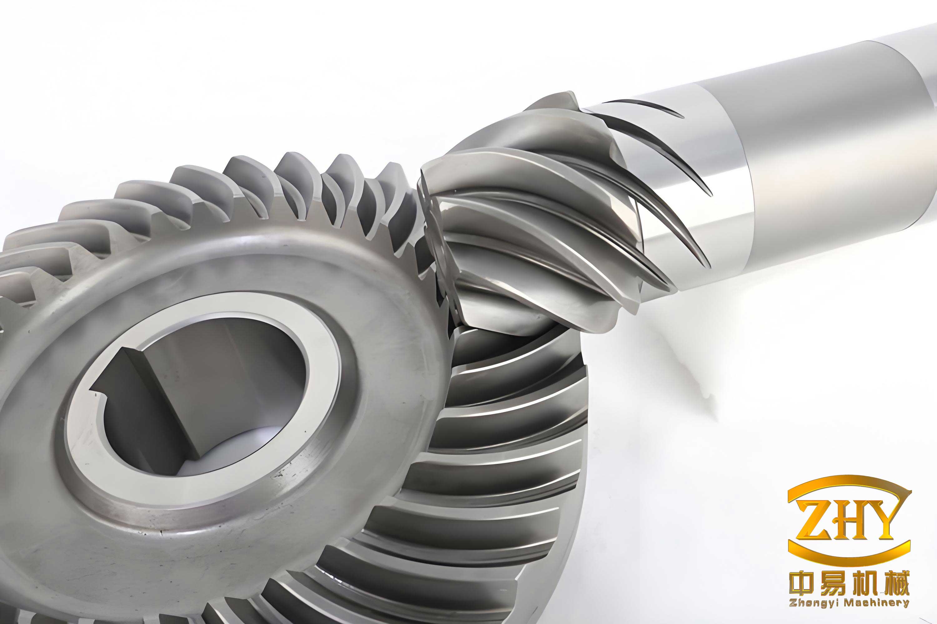
To simulate the NC machining of spiral bevel gears, I used VERICUT, a specialized software for virtual machining. The simulation begins with defining the gear parameters. For instance, consider a spiral bevel gear pair with the following specifications, which are essential for designing the cutter and simulation setup. These parameters are summarized in the table below, highlighting key dimensions for the spiral bevel gear.
| Parameter | Pinion | Gear (Large Wheel) |
|---|---|---|
| Number of Teeth | 16 | 47 |
| Module $m$ (mm) | 3.5 | |
| Spiral Angle (°) | 35 | |
| Pressure Angle (°) | 20 | |
| Shaft Angle (°) | 90 | |
| Face Width $b$ (mm) | 21 | |
The cutter for machining the spiral bevel gear’s large wheel is designed based on calculated parameters. The cutter geometry influences the tooth profile accuracy, and its parameters are derived from the gear specifications. Below is a table summarizing the cutter parameters for the spiral bevel gear’s large wheel.
| Cutter Parameter | Value |
|---|---|
| Cutter Diameter (mm) | 152.4 |
| Blade Edge Width (mm) | 2 |
| Outer Blade Tip Diameter (mm) | 154.4 |
| Inner Blade Tip Diameter (mm) | 150.4 |
| Inner Blade Pressure Angle | 21°15′ |
| Outer Blade Pressure Angle | -18°45′ |
In VERICUT, I created a simplified 3D model of the cutter by revolving its cross-section around the axis. The tool manager in VERICUT allows for precise definition of the cutter geometry, which is crucial for accurate simulation of the spiral bevel gear machining. Next, the NC machine model is configured by setting the motion parameters for the X, Y, Z, A, and B axes. The machine structure mimics a five-axis mill, where the workpiece moves linearly and rotates, while the cutter is fixed in orientation but moves radially. The motion parameters are defined based on the coordinate transformations discussed earlier, ensuring that the virtual machine replicates the actual NC machine behavior for spiral bevel gear production.
The simulation process involves importing the gear blank model, typically created in CAD software like UG, into VERICUT. The blank is positioned according to the machine coordinates, and the NC program, generated from the post-processed toolpath, is loaded. During simulation, VERICUT visually displays the material removal process, allowing for real-time detection of issues such as overcut or undercut. For the spiral bevel gear’s large wheel, I ran the simulation step-by-step, observing the generation of each tooth slot. The simulation output at different time instances shows the progressive cutting action, and the final result is a virtual machined spiral bevel gear model. This model can be compared with the design intent to validate the NC program’s accuracy.
To validate the simulation, a design model of the spiral bevel gear is created using UG software. The tooth surface points, calculated from the gear geometry equations, are imported into UG. These points are connected to form curves, which are then used to generate surfaces through functions like lofting or net surface creation. The individual tooth surfaces are mirrored and patterned to form the complete gear model. This design model serves as a reference for virtual measurement. The table below shows a sample of tooth surface point coordinates used for modeling the spiral bevel gear.
| Point ID | X-coordinate (mm) | Y-coordinate (mm) | Z-coordinate (mm) |
|---|---|---|---|
| 1 | 45.23 | 12.67 | 0.00 |
| 2 | 44.89 | 13.45 | 0.12 |
| 3 | 44.50 | 14.20 | 0.25 |
| 4 | 44.05 | 14.92 | 0.38 |
| 5 | 43.55 | 15.60 | 0.52 |
The design model is exported in STL format and imported into VERICUT’s measurement module. Here, the virtual machined spiral bevel gear model is compared against the design model. The measurement involves aligning the two models and calculating the deviations at sampled points on the tooth surface. The error distribution is analyzed to ensure it falls within acceptable tolerances, typically within micrometers for precision spiral bevel gears. The measurement results can be visualized as color maps or numerical reports, confirming the feasibility of the NC machining process. For instance, the root mean square (RMS) error might be computed as:
$$ \text{RMS Error} = \sqrt{\frac{1}{N} \sum_{i=1}^{N} (d_i)^2} $$
where $d_i$ is the deviation at the $i$-th point and $N$ is the total number of points. This virtual measurement eliminates the need for physical coordinate measuring machines (CMMs) during the prototyping phase, saving time and resources.
Throughout this simulation and measurement process, the importance of spiral bevel gear accuracy cannot be overstated. The geometry of a spiral bevel gear is defined by complex equations involving parameters like spiral angle, pressure angle, and tooth curvature. For example, the tooth surface equation for a spiral bevel gear can be expressed using differential geometry. In a simplified form, the position vector of a point on the tooth surface in the workpiece coordinate system is given by:
$$ \mathbf{r}(u, v) = \begin{bmatrix} x(u, v) \\ y(u, v) \\ z(u, v) \end{bmatrix} $$
where $u$ and $v$ are parameters related to the cutter path and gear rotation. The normal vector $\mathbf{n}$ is derived from partial derivatives:
$$ \mathbf{n} = \frac{\partial \mathbf{r}}{\partial u} \times \frac{\partial \mathbf{r}}{\partial v} $$
This mathematical representation is used in both the design and simulation stages to ensure consistency. In VERICUT, the cutter engagement is simulated based on these equations, with the material removal rate calculated using Boolean operations between the tool and workpiece volumes.
Moreover, the NC program optimization for spiral bevel gears involves iterative adjustments to minimize errors. The toolpath is generated using algorithms that consider the cutter contact conditions. For instance, the feed rate $f$ might be adjusted based on the curvature $\kappa$ of the spiral bevel gear tooth to avoid gouging:
$$ f = f_0 \cdot \exp(-\alpha \kappa) $$
where $f_0$ is the nominal feed rate and $\alpha$ is a damping factor. Such refinements are part of the simulation feedback loop, where virtual measurement results are used to tweak the NC code before actual machining.
In conclusion, the use of VERICUT for NC machining simulation and virtual measurement of spiral bevel gears offers significant advantages. It validates the NC programming approach, reduces the need for physical trials, and shortens the design-to-production cycle. The simulation accurately replicates the machining process, and the virtual measurement ensures that the machined spiral bevel gear meets design specifications. This methodology not only enhances productivity but also supports the high-precision demands of industries relying on spiral bevel gears. Future work could involve integrating thermal and dynamic effects into the simulation for even more realistic predictions.
To further elaborate on the coordinate transformation, let me detail the homogeneous matrices. The matrix $M_{om}$ from the machine coordinate system to the workpiece fixed system is:
$$ M_{om} = \begin{bmatrix}
\cos \delta_m & 0 & \sin \delta_m & -X – X_B \sin \delta_m \\
0 & 1 & 0 & E \\
-\sin \delta_m & 0 & \cos \delta_m & -X_B \cos \delta_m \\
0 & 0 & 0 & 1
\end{bmatrix} $$
where $\delta_m$ is the workpiece installation angle, $E$ is the vertical offset, $X_B$ is the machine bed position, and $X$ is the axial correction. The matrix $M_{wo}$ for rotation is:
$$ M_{wo} = \begin{bmatrix}
1 & 0 & 0 & 0 \\
0 & \cos \Phi_1 & -\sin \Phi_1 & 0 \\
0 & \sin \Phi_1 & \cos \Phi_1 & 0 \\
0 & 0 & 0 & 1
\end{bmatrix} $$
These transformations are fundamental for accurate simulation of spiral bevel gear machining. In the NC machine, the equivalent motions are computed by solving inverse kinematics. For example, the coordinates in the NC machine system $\sum_{m’}$ are derived from $R_w$ and $c_w$ through additional transformations specific to the machine topology.
The virtual measurement process in VERICUT includes statistical analysis. The table below summarizes typical error metrics for a spiral bevel gear after simulation and measurement.
| Error Metric | Value (μm) | Tolerance Limit (μm) |
|---|---|---|
| Maximum Positive Error | +5.2 | +10 |
| Maximum Negative Error | -4.8 | -10 |
| Mean Absolute Error | 2.3 | 5 |
| RMS Error | 2.7 | 6 |
These results demonstrate that the NC machining simulation for spiral bevel gears is feasible and reliable. The integration of VERICUT with CAD software like UG creates a seamless digital workflow, from design to virtual validation. This approach is particularly beneficial for custom spiral bevel gears, where batch sizes are small and precision requirements are high.
In summary, the simulation and measurement of spiral bevel gears using VERICUT represent a modern solution to an age-old manufacturing challenge. By leveraging digital twins, manufacturers can achieve faster time-to-market, reduced costs, and improved quality for spiral bevel gears. The continuous refinement of simulation algorithms will further enhance the accuracy and efficiency of spiral bevel gear production in the future.