
I began this study because the helical gear transmission in a high-speed rail bogie is one of the most important parts of the vehicle. The performance of the helical gear pair directly affects safety, ride comfort, noise, and vibration. In actual service, the helical gear pair must operate under time-varying load, manufacturing error, assembly error, and side clearance. Among these factors, side clearance is especially important because it changes the contact state, the impact intensity, and the stress distribution of the helical gear pair. My aim was to build a parametric helical gear pair, analyze its dynamic behavior under different side clearances, and then apply reasonable modification methods to improve its transmission performance.
I selected a high-speed rail helical gear pair as the research object. The helical gear pair has a normal module of 6 mm, a pressure angle of 20 degrees, and a helix angle of 17.5 degrees. The pinion has 35 teeth and the gear has 85 teeth. The face width of both the pinion and the gear is 68 mm. I used these parameters to calculate all transverse dimensions and to build a three-dimensional model. The basic parameters are summarized in Table 1.
| Parameter | Unit | Pinion | Gear |
|---|---|---|---|
| Normal module | mm | 6 | 6 |
| Number of teeth | — | 35 | 85 |
| Normal pressure angle | degree | 20 | 20 |
| Helix angle | degree | 17.5 | 17.5 |
| Addendum coefficient | — | 1.05 | 1.05 |
| Dedendum coefficient | — | 0.3 | 0.3 |
| Face width | mm | 68 | 68 |
For a helical gear, the normal plane parameters are standard, while the transverse parameters are obtained from the normal parameters and the helix angle. I used the following relationships. The transverse module is
$$m_t = \frac{m_n}{\cos\beta}$$
The transverse pressure angle is
$$\alpha_t = \arctan\left(\frac{\tan\alpha_n}{\cos\beta}\right)$$
The transverse addendum coefficient and dedendum coefficient are
$$h_{at}^{*} = h_{an}^{*}\cos\beta$$
$$c_t^{*} = c_n^{*}\cos\beta$$
The addendum and dedendum are
$$h_a = h_{an}^{*}m_n$$
$$h_f = (h_{an}^{*} + c_n^{*})m_n$$
The reference diameter, tip diameter, root diameter, and base diameter of the helical gear are
$$d = m_t z$$
$$d_a = d + 2h_a$$
$$d_f = d – 2h_f$$
$$d_b = d\cos\alpha_t$$
Using these equations, I obtained the geometric dimensions shown in Table 2. These values were used as the foundation for the subsequent parametric model and finite element analysis.
| Item | Unit | Pinion | Gear |
|---|---|---|---|
| Reference diameter | mm | 220.1911 | 534.7499 |
| Tip diameter | mm | 232.7911 | 547.3499 |
| Root diameter | mm | 203.9911 | 518.5499 |
| Base diameter | mm | 205.7309 | 499.6039 |
To create the involute profile, I used the geometric property of the involute of a circle. When a straight line rolls without slipping on the base circle, a point on the line traces the involute. In Cartesian coordinates, the involute can be written as
$$x = r_b(\cos u + u\sin u)$$
$$y = r_b(\sin u – u\cos u)$$
where \(r_b\) is the base radius and \(u\) is the involute parameter. For the helical gear, the tooth surface is generated by sweeping the involute profile along a helix. The helix can be expressed as
$$x = r\cos\theta$$
$$y = r\sin\theta$$
$$z = \pm \frac{h\theta}{2\pi}$$
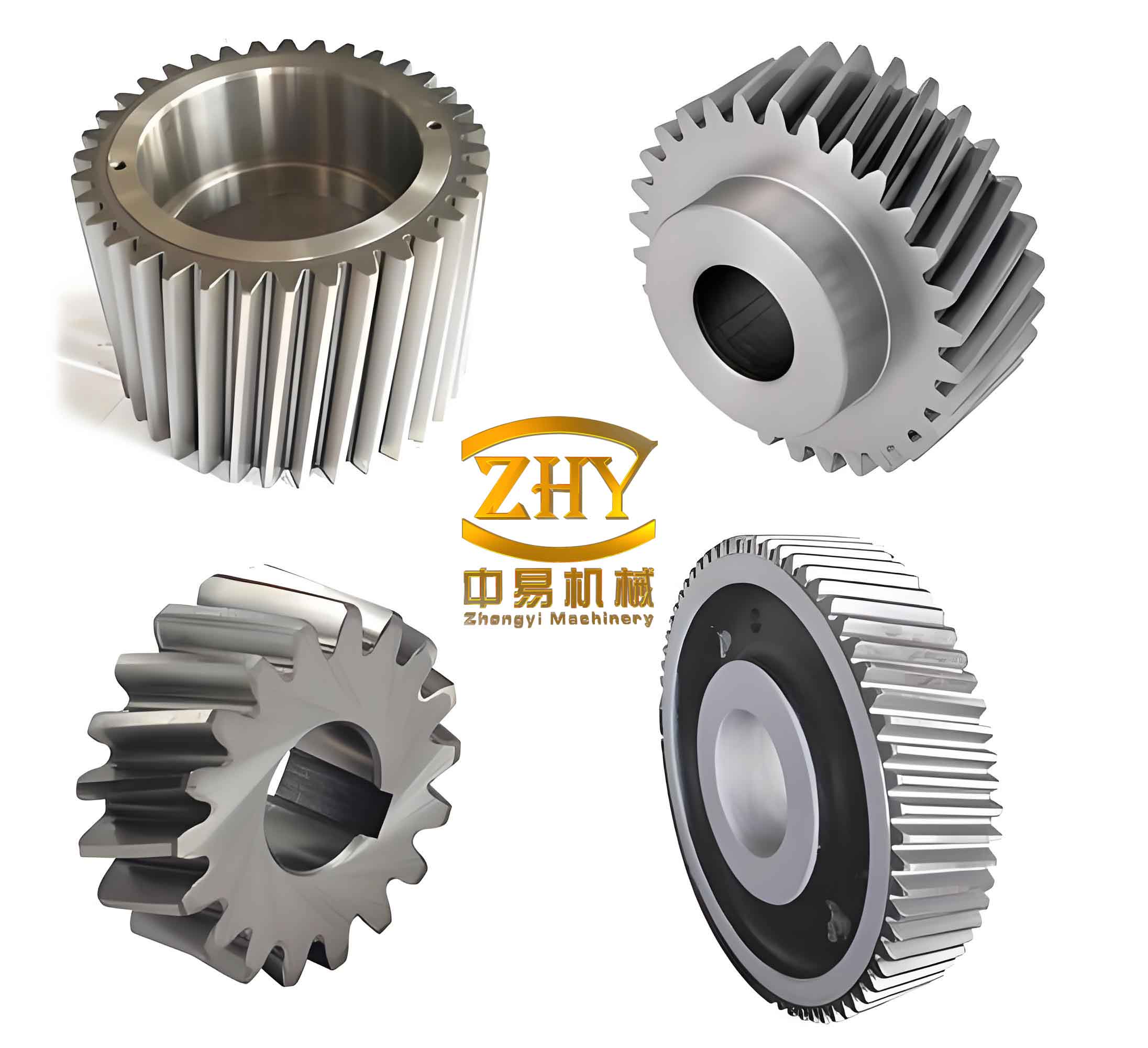
where \(r\) is the radius of the cylinder, \(\theta\) is the angular parameter, and \(h\) is the lead. I used these equations in the parametric modeling environment to generate the tooth flank accurately. I first created the root circle, tip circle, reference circle, and base circle. Then I generated the involute curve and mirrored it to form a complete tooth profile. After that, I swept the profile along the helix and patterned the tooth around the axis. Finally, I assembled the pinion and the gear with a controlled center distance and a defined side clearance. The resulting helical gear pair is shown below.
Side clearance is a key factor in a helical gear pair. In a gear transmission, side clearance is the gap between the non-working tooth flanks when the working tooth flanks are in contact. It is usually classified into circumferential backlash, normal backlash, and radial backlash. Circumferential backlash is the maximum arc length on the pitch circle when one gear is fixed and the other is rotated. Normal backlash is the shortest distance between the non-working flanks along the common normal. Radial backlash is the reduction in center distance until both working and non-working flanks contact. These definitions are important because they describe the same physical condition from different measurement directions.
Side clearance has several functions. First, it compensates for thermal expansion caused by heat generation during operation. Second, it allows lubricant to be stored on the tooth surface and helps form an oil film. Third, it compensates for manufacturing and assembly errors. However, side clearance also has negative effects. If the clearance is too small, the helical gear pair may become jammed, transmission efficiency may decrease, and the tooth surface may be damaged by excessive friction. If the clearance is too large, the effective tooth thickness decreases, impact between teeth increases, and the helical gear pair may generate strong vibration and noise. Therefore, the side clearance must be reasonably designed.
The factors that influence side clearance include center distance error, manufacturing error, temperature, lubrication condition, parallelism error of the axes, and elastic deformation under load. Among these factors, center distance error is one of the most direct and controllable factors. I derived the relationship between center distance and normal backlash. For a pair of involute helical gears, the transverse backlash can be expressed as
$$j_{bt} = e_{b2} – s_{b1} + 2(r_{b1} + r_{b2})\operatorname{inv}\alpha_{wt}$$
where \(e_{b2}\) is the base circle tooth space width of the gear, \(s_{b1}\) is the base circle tooth thickness of the pinion, \(r_{b1}\) and \(r_{b2}\) are the base radii, and \(\alpha_{wt}\) is the operating transverse pressure angle. The normal backlash is
$$j_{bn} = j_{bt}\cos\beta_b$$
where \(\beta_b\) is the base helix angle. An equivalent expression is
$$j_{bn} = p_{bn} – (s_{bn1} + s_{bn2}) + 2(r_{b1} + r_{b2})\operatorname{inv}\alpha_{wt}\cos\beta_b$$
The operating transverse pressure angle is related to the center distance by
$$\cos\alpha_{wt} = \frac{r_{b1} + r_{b2}}{a_w}$$
where \(a_w\) is the operating center distance. This equation shows that when the center distance changes, the operating pressure angle changes, and the normal backlash changes accordingly. Using this relationship, I calculated three representative side clearance values, as shown in Table 3.
| Center distance (mm) | Operating pressure angle (degree) | Normal backlash (mm) |
|---|---|---|
| 380.1 | 21.90 | 0.13 |
| 380.2 | 21.95 | 0.27 |
| 380.3 | 21.98 | 0.39 |
After building the parametric helical gear pair, I imported the model into ANSYS Workbench for finite element analysis. I assigned the material properties of 20CrMoTi to both the pinion and the gear. The material data are listed in Table 4. I used a surface-hardened treatment for the tooth surface in the conceptual design, and the elastic modulus, Poisson ratio, and density were defined as shown.
| Property | Value | Unit |
|---|---|---|
| Density | 7850 | kg/m3 |
| Poisson ratio | 0.31 | — |
| Elastic modulus | 206 | GPa |
For contact modeling, I selected a flexible-to-flexible contact because both the pinion and the gear are deformable bodies with similar stiffness. I used a surface-to-surface contact pair. The tooth flanks of the pinion were set as the contact surface, and the tooth flanks of the gear were set as the target surface. Among the available contact algorithms, I chose an augmented Lagrange method because it controls penetration while maintaining reasonable convergence. I also used a face-to-face contact formulation because the helical gear pair undergoes relative sliding along the contact line, and the contact position changes continuously during meshing.
Mesh quality has a strong influence on the accuracy of the helical gear contact analysis. I used a hexahedron-dominant mesh and refined the mesh near the contact region. The element size in the contact region was set to 5 mm, while the element size in the non-contact region was set to 10 mm. The final finite element model contained 1,022,711 nodes and 221,480 elements. This mesh density provided a good balance between accuracy and computational cost for the helical gear pair.
For load application, I considered the actual operating conditions of a high-speed rail traction motor. The rated power was 455 kW, and I selected the starting condition with an input torque of 2900 N·m as the main load case. I applied a rotational speed of 25 rad/s to the pinion and a resisting torque of 2900 N·m to the gear. The load step settings are given in Table 5. I used a solution time of 1 s, an initial number of substeps of 30, a minimum number of substeps of 20, and a maximum number of substeps of 100. Large deflection was activated to account for the deformation of the helical gear teeth.
| Control item | Value |
|---|---|
| Solution time | 1 s |
| Initial substeps | 30 |
| Minimum substeps | 20 |
| Maximum substeps | 100 |
Before the transient dynamic analysis, I used Hertz contact theory to estimate the theoretical contact stress of the helical gear pair. For two elastic cylinders in line contact, the contact half-width is
$$b = \sqrt{\frac{4F_{bn}}{\pi L} \frac{\frac{1-\nu_1^2}{E_1} + \frac{1-\nu_2^2}{E_2}}{\frac{1}{R_1} + \frac{1}{R_2}}}$$
where \(F_{bn}\) is the normal load, \(L\) is the contact line length, \(\nu_1\) and \(\nu_2\) are the Poisson ratios, \(E_1\) and \(E_2\) are the elastic moduli, and \(R_1\) and \(R_2\) are the equivalent radii of curvature at the meshing point. The maximum contact pressure is
$$\sigma_H = \frac{2F_{bn}}{\pi b L}$$
For a helical gear pair, the contact stress can also be written in the standard form
$$\sigma_H = Z_E Z_H Z_\beta Z_\varepsilon \sqrt{\frac{F_t}{d_1 B}\frac{u+1}{u}}$$
where \(Z_E\) is the elastic coefficient, \(Z_H\) is the zone factor, \(Z_\beta\) is the helix angle factor, \(Z_\varepsilon\) is the contact ratio factor, \(F_t\) is the transverse tangential force, \(d_1\) is the pinion reference diameter, \(B\) is the face width, and \(u\) is the gear ratio. Using the material and geometry parameters, I calculated a theoretical contact stress of about 1024.3 MPa. The allowable stress of the surface-hardened 20CrMoTi helical gear is about 1600 MPa, so the strength condition is satisfied.
I then performed modal analysis to obtain the natural frequencies and mode shapes of the helical gear pair. The general vibration equation is
$$[M]\{\ddot{x}\} + [C]\{\dot{x}\} + [K]\{x\} = \{F(t)\}$$
For free vibration without damping, the equation reduces to
$$[M]\{\ddot{x}\} + [K]\{x\} = \{0\}$$
Assuming a harmonic solution, the eigenvalue problem is
$$([K] – \omega^2[M])\{u\} = \{0\}$$
where \(\omega\) is the natural frequency and \(\{u\}\) is the mode shape vector. I fixed the rotational degrees of freedom except for the rotation about the gear axis and solved for the first ten natural frequencies. The results are shown in Table 6. The first natural frequency is 1432.6 Hz. The meshing frequency of the helical gear pair is
$$f = \frac{zn}{60}$$
Using the pinion speed and tooth number, the meshing frequency is about 875 Hz, which is well below the first natural frequency. This indicates that the helical gear pair is not likely to resonate under the selected operating condition. The modal results also provide a useful reference for avoiding resonance during design and operation.
| Mode order | Natural frequency (Hz) |
|---|---|
| 1 | 1432.6 |
| 2 | 1462.3 |
| 3 | 1551.7 |
| 4 | 1665.5 |
| 5 | 1792.8 |
| 6 | 2090.9 |
| 7 | 2616.7 |
| 8 | 2649.7 |
| 9 | 2982.3 |
| 10 | 3611.7 |
The first six mode shapes showed different vibration patterns. The first and second modes were bending vibrations in two orthogonal directions. The third mode was an umbrella-like mode. The fourth mode was a four-point folding mode. The fifth mode was a circumferential mode, and the sixth mode was a torsional mode. The higher the mode order, the more complex the deformation of the helical gear pair. These results help me understand which vibration modes should be avoided in practical operation.
After modal analysis, I performed transient dynamic analysis for the three side clearance cases. I used the full method because it can handle surface-to-surface contact and large deformation while providing high accuracy. The transient dynamic equation is
$$[M]\{\ddot{u}\} + [C]\{\dot{u}\} + [K]\{u\} = \{F(t)\}$$
I applied the same boundary conditions and load steps as in the modal analysis. For each side clearance, I extracted the maximum equivalent stress, the contact pressure, and the time history of the maximum equivalent stress. The results before modification are summarized in Table 7. When the side clearance was 0.13 mm, the maximum equivalent stress was 969.51 MPa and the maximum contact pressure was 607.88 MPa. When the side clearance increased to 0.27 mm, the maximum equivalent stress increased to 1263.9 MPa and the maximum contact pressure increased to 1150.8 MPa. When the side clearance increased to 0.39 mm, the maximum equivalent stress reached 1363.8 MPa and the maximum contact pressure reached 1274.6 MPa.
| Side clearance (mm) | Maximum equivalent stress (MPa) | Maximum contact pressure (MPa) |
|---|---|---|
| 0.13 | 969.51 | 607.88 |
| 0.27 | 1263.9 | 1150.8 |
| 0.39 | 1363.8 | 1274.6 |
The transient results showed that the maximum equivalent stress and the maximum contact pressure both increased as the side clearance increased. The maximum equivalent stress was concentrated near the tooth tip corners and along the contact line. The contact pressure was distributed near the contact line, but the ends of the tooth also carried a relatively high pressure. This indicates that the load distribution along the face width was not uniform. The time history of the maximum equivalent stress also showed stronger fluctuations when the side clearance was larger. These fluctuations are caused by the impact between the meshing teeth. For a high-speed rail helical gear pair, this impact can cause vibration, noise, and even fatigue failure at the tooth root or tooth tip. Therefore, I concluded that the helical gear pair should be modified to improve its dynamic performance.
I considered two modification strategies: profile modification and axial modification. Profile modification is used to reduce the impact at the beginning and end of meshing. For a helical gear pair, the meshing process involves multiple tooth pairs, and the actual base pitch differs from the theoretical base pitch because of elastic deformation and manufacturing error. This difference causes interference at the tooth tip and tooth root. Profile modification removes a small amount of material from the tooth tip or tooth root to compensate for this interference. I used a long profile modification because the axial contact ratio of the helical gear pair is relatively large. The modification length was determined as
$$L = 1.2 m_n = 7.26 \text{ mm}$$
I used a parabolic modification curve, which can be written as
$$\Delta x = \Delta_{\max}\left[0.44\frac{x}{L} + 0.56\left(\frac{x}{L}\right)^2\right]$$
where \(\Delta_{\max}\) is the maximum modification amount and \(x\) is the relative coordinate along the line of action. I determined the maximum modification amount from the precision grade. For a 7th-grade helical gear with a normal module of 6 mm, the coefficient \(e\) was taken as 0.009. Therefore, the maximum modification amount was
$$\Delta_{\max} = m e = 6 \times 0.009 = 0.054 \text{ mm}$$
I applied profile modification only to the pinion tooth tip and left the gear unmodified. After profile modification, I repeated the transient dynamic analysis for the three side clearance cases. The results are shown in Table 8. For a side clearance of 0.13 mm, the maximum equivalent stress decreased to 806.19 MPa and the maximum contact pressure decreased to 349.69 MPa. For a side clearance of 0.27 mm, the maximum equivalent stress decreased to 948.02 MPa and the maximum contact pressure decreased to 830.78 MPa. For a side clearance of 0.39 mm, the maximum equivalent stress decreased to 1117.4 MPa and the maximum contact pressure decreased to 865.21 MPa.
| Side clearance (mm) | Maximum equivalent stress after profile modification (MPa) | Maximum contact pressure after profile modification (MPa) |
|---|---|---|
| 0.13 | 806.19 | 349.69 |
| 0.27 | 948.02 | 830.78 |
| 0.39 | 1117.4 | 865.21 |
The profile modification results showed that the maximum equivalent stress was reduced by about 17 percent for the 0.13 mm case, about 25 percent for the 0.27 mm case, and about 18 percent for the 0.39 mm case. The maximum contact pressure was reduced even more significantly. The stress concentration at the tooth tip was clearly alleviated. The maximum equivalent stress shifted toward the middle of the tooth and the contact line region, which is more favorable for load carrying. The time history of the maximum equivalent stress after profile modification was also smoother than that before modification. This indicates that profile modification reduces the meshing impact and improves the dynamic performance of the helical gear pair.
I then studied axial modification. Axial modification is used to compensate for load concentration along the face width. In a helical gear pair, axial load distribution can become uneven because of shaft deformation, bearing deformation, gearbox deformation, centrifugal force, and side clearance. The purpose of axial modification is to make the contact area more uniform and to avoid edge contact. Common axial modification methods include helix angle modification, tooth end relief, and crowning. For this high-speed and heavy-load helical gear pair, I selected helix angle modification because it can compensate for the angular misalignment caused by elastic deformation and improve the load distribution along the contact line.
For helix angle modification, the modification amount is determined from the equivalent misalignment. The relationship can be written as
$$\Delta\beta = \frac{F_{\beta x}}{F_t/(b C_r)} = \frac{F_{\beta x} b C_r}{F_t}$$
where \(\Delta\beta\) is the helix angle modification amount, \(F_{\beta x}\) is the equivalent misalignment, \(F_t\) is the transverse tangential force, \(b\) is the face width, and \(C_r\) is the meshing stiffness. Based on the calculated deformation and load, I obtained a helix angle modification amount of 0.32 degrees. Thus, the modified helix angle became
$$\beta = 17.5^\circ + 0.32^\circ = 17.82^\circ$$
I applied this helix angle modification to the pinion only. After modification, I performed transient dynamic analysis again for the three side clearance cases. The results are summarized in Table 9. For a side clearance of 0.13 mm, the maximum equivalent stress decreased to 727.65 MPa and the maximum contact pressure decreased to 469.7 MPa. For a side clearance of 0.27 mm, the maximum equivalent stress decreased to 826.11 MPa and the maximum contact pressure decreased to 532.9 MPa. For a side clearance of 0.39 mm, the maximum equivalent stress decreased to 997.87 MPa and the maximum contact pressure decreased to 639.4 MPa.
| Side clearance (mm) | Maximum equivalent stress after helix modification (MPa) | Maximum contact pressure after helix modification (MPa) |
|---|---|---|
| 0.13 | 727.65 | 469.7 |
| 0.27 | 826.11 | 532.9 |
| 0.39 | 997.87 | 639.4 |
The helix angle modification results showed that the maximum equivalent stress decreased by about 25 percent for the 0.13 mm case, about 34 percent for the 0.27 mm case, and about 27 percent for the 0.39 mm case. The maximum contact pressure decreased by about 23 percent, 53 percent, and 50 percent for the three cases, respectively. The contact area became larger, and the maximum stress was located near the middle of the tooth instead of at the tooth ends. This means that the axial load distribution was improved and the edge contact was reduced. The time history of the maximum equivalent stress after helix angle modification was smoother than before modification. Therefore, helix angle modification is effective for reducing vibration, noise, and stress concentration in the helical gear pair.
To compare the two modification methods more clearly, I summarized the maximum equivalent stress reduction ratios in Table 10. Both profile modification and helix angle modification reduced the maximum equivalent stress and contact pressure. Profile modification was more effective for reducing the tooth tip impact and smoothing the stress history. Helix angle modification was more effective for improving the load distribution along the face width and reducing the edge contact. The best modification strategy depends on the dominant failure mode and the operating condition. For a high-speed rail helical gear pair with side clearance, a combination of profile modification and helix angle modification may provide the best overall performance, although each method alone already produced clear benefits.
| Side clearance (mm) | Stress reduction by profile modification | Stress reduction by helix modification |
|---|---|---|
| 0.13 | About 17 percent | About 25 percent |
| 0.27 | About 25 percent | About 34 percent |
| 0.39 | About 18 percent | About 27 percent |
From all the analyses, I draw several conclusions. First, side clearance has a direct and significant influence on the dynamic behavior of a helical gear pair. As the side clearance increases, the maximum equivalent stress and the maximum contact pressure both increase. The impact between the meshing teeth becomes stronger, and the stress concentration near the tooth tip and contact line becomes more severe. Second, the maximum equivalent stress is usually located at the tooth tip corner and along the contact line. This location is prone to fatigue damage, so the helical gear pair should be modified to reduce the stress concentration. Third, profile modification can effectively reduce the meshing impact and smooth the stress history. Fourth, helix angle modification can effectively improve the axial load distribution and reduce edge contact. Both modification methods improve the dynamic performance of the helical gear pair, but their effects are different. A reasonable modification design should be selected according to the actual operating condition.
For the high-speed rail helical gear pair studied here, the transient dynamic analysis showed that the maximum equivalent stress under the largest side clearance was still below the allowable stress, but it was close to the allowable limit. The maximum contact pressure also increased significantly with side clearance. Therefore, relying only on the original design is not sufficient for long-term reliable operation. Profile modification and helix angle modification both provide a practical way to improve the transmission performance. I found that helix angle modification was especially effective for reducing the maximum contact pressure, while profile modification was especially effective for smoothing the time history of the maximum equivalent stress. A combined modification strategy may further improve the dynamic performance of the helical gear pair and extend its service life.
Finally, I note some limitations of my work. I considered only the center distance error as the source of side clearance. Other factors, such as axis parallelism error, manufacturing error of the tooth flank, and clearance between the shaft and the gear bore, were not included. These factors may also affect the contact state and dynamic response of the helical gear pair. In future work, I would like to build a more comprehensive model that includes multiple error sources and more side clearance levels. I would also like to study crowning modification and tooth end relief in more detail, because these methods may provide additional benefits for high-speed rail helical gear transmissions. Despite these limitations, the results of this study provide a useful reference for the dynamic analysis and modification design of high-speed rail helical gears.