
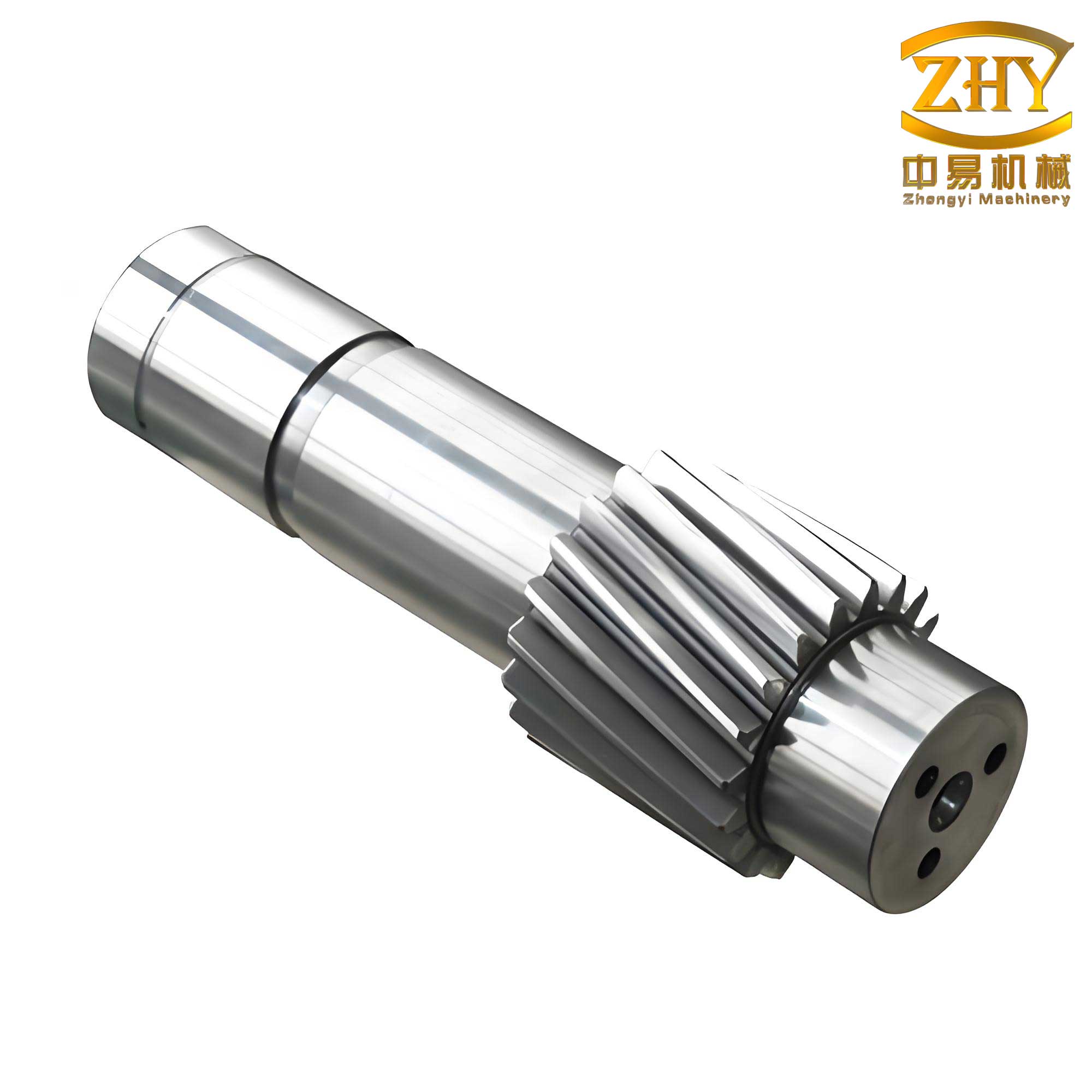
In the manufacturing industry, the processing of gear shafts has long been a critical yet challenging task. Traditional methods rely heavily on manual labor for operations such as loading, unloading, grinding, and alignment, leading to high labor intensity, poor working conditions, and inconsistent efficiency. As a result, companies face issues like high employee turnover, increased management difficulty, and compromised product quality and output. In my perspective, the integration of industrial robots into the grinding process for gear shafts offers a transformative solution. This article presents my design of an automated grinding system for gear shafts, leveraging industrial robots to enhance productivity, precision, and flexibility. I will delve into the system’s components, operational workflow, and technical specifications, emphasizing the importance of gear shafts in automotive applications and using tables and formulas to summarize key aspects.
The demand for automation in gear shaft grinding stems from several inherent drawbacks in manual processes. When human operators handle multiple CNC machines simultaneously, variability in performance can cause defects, such as damage during handling of gear shafts, reducing yield rates. Moreover, with rising labor costs and recruitment challenges in manufacturing, automating these tasks becomes economically imperative. From my experience, industrial robots provide stability, repeatability, and 24/7 operational capability, making them ideal for high-volume production of gear shafts. By replacing manual interventions, robots can minimize errors, ensure consistent quality, and boost throughput. I propose that an automated loading and unloading system, integrated with CNC grinders, is essential to address these issues. This system not only reduces reliance on human labor but also adapts to diverse product lines through programmable flexibility, highlighting the centrality of gear shafts in modern automotive components.
My overall conception of the automated grinding system revolves around a collaborative setup involving industrial robots, CNC grinders, and auxiliary equipment. The system aims to streamline the entire grinding process for gear shafts, from raw material handling to finished part output. Key advantages include enhanced automation control, integrated functionality for transport and clamping, and reliable operation via robotic end-effectors. I envision a layout where two CNC grinders (Grinder A and Grinder B) are positioned opposite each other, with a robot in the center and a feeding mechanism nearby. This configuration allows the robot to efficiently manage loading and unloading tasks across three workstations, optimizing space and workflow. The system’s core is a programmable logic controller (PLC) that coordinates all devices, enabling real-time monitoring and control. In my design, this setup significantly improves the grinding of gear shafts by reducing cycle times and minimizing human error, as shown in Table 1 summarizing system components.
| Component | Function | Specifications |
|---|---|---|
| Industrial Robot | Handles loading, unloading, and transfer of gear shafts | Model: TX90; Payload: 7 kg; Reach: 1000 mm; Degrees of Freedom: 6 |
| CNC Grinder A | Performs grinding operations on gear shafts | Automated clamping; Integration with PLC |
| CNC Grinder B | Secondary grinding station for gear shafts | Similar to Grinder A; Enables parallel processing |
| Feeding Mechanism | Stores and positions raw gear shafts for robot access | Capacity: Multiple gear shafts; Precision alignment |
| Programmable Logic Controller (PLC) | Central control unit for system coordination | Touchscreen interface; Real-time communication |
| End-Effector (Robotic Gripper) | Grips and releases gear shafts during operations | Two-finger design; Pneumatic actuation; Magnetic sensors |
To quantify the benefits, I consider the grinding force involved in processing gear shafts. The grinding force \( F_g \) can be expressed as a function of material properties and operational parameters:
$$ F_g = k \cdot v_s \cdot a_p \cdot b_w $$
where \( k \) is a material constant specific to gear shaft steel, \( v_s \) is the grinding wheel speed, \( a_p \) is the depth of cut, and \( b_w \) is the width of cut. In automated systems, robots can maintain optimal parameters consistently, reducing variations that affect gear shaft quality. For instance, by controlling \( a_p \) precisely, the robot minimizes over-grinding, which is crucial for the dimensional accuracy of gear shafts. My design incorporates feedback loops to adjust these parameters in real-time, ensuring that each gear shaft meets stringent tolerances.
The selection of an industrial robot is pivotal in my system. After evaluating various models, I chose the TX90 robot due to its high flexibility, multiple degrees of freedom, and suitability for handling gear shafts. Its payload capacity of 7 kg accommodates typical gear shafts used in automotive applications, and a reach of 1000 mm allows access to multiple workstations. The robot’s programming language, VAL3, supports modular code development similar to C, enabling complex routines for grinding tasks. In my experience, this robot enhances productivity by performing repetitive motions with minimal deviation, critical for the precision grinding of gear shafts. Table 2 details the robot’s specifications, emphasizing its role in automating gear shaft processes.
| Parameter | Value | Significance for Gear Shafts |
|---|---|---|
| Rated Load | 7 kg | Sufficient for most automotive gear shafts |
| Maximum Load | 20 kg | Allows handling of heavier gear shafts if needed |
| Working Radius | 1000 mm | Enables access to grinders and feeders for gear shafts |
| Degrees of Freedom | 6 | Provides dexterity for complex maneuvers with gear shafts |
| Repeatability | ±0.05 mm | Ensures precise positioning of gear shafts during grinding |
| Programming Language | VAL3 | Facilitates easy integration and control for gear shaft tasks |
The system configuration involves a spatial layout that maximizes efficiency. I position Grinder A and Grinder B facing each other, with the robot at the center and a feeding mechanism adjacent. This arrangement minimizes robot movement distances, reducing cycle times for processing gear shafts. The feeding mechanism stores raw gear shafts in a magazine, which are then picked by the robot and transferred to the grinders. After grinding, the robot places finished gear shafts onto a conveyor or output tray. My design includes safety interlocks and sensors to prevent collisions, ensuring smooth operation. The integration of all components is managed by the PLC, which acts as the brain of the system. It receives signals from devices, triggers grinding cycles, and monitors the status of gear shafts throughout the process. Figure 1 illustrates this layout, though in text, I emphasize that the robot’s path is optimized using kinematic equations. For a robot with six degrees of freedom, the position of the end-effector relative to the base can be described by a transformation matrix:
$$ T = \begin{bmatrix} R & p \\ 0 & 1 \end{bmatrix} $$
where \( R \) is a 3×3 rotation matrix and \( p \) is a 3×1 translation vector. This allows precise control over the handling of gear shafts, ensuring they are accurately placed in grinders.
The electrical control system is the backbone of my automated grinding system for gear shafts. I implement a PLC-based architecture that coordinates the robot, grinders, and peripherals. The PLC features a touchscreen interface for human-machine interaction, allowing operators to start, stop, and monitor the system. In my design, the PLC executes a programmed sequence: it activates the feeding mechanism to present a raw gear shaft, commands the robot to pick it, directs the robot to load it into Grinder A, initiates grinding, and then manages unloading and transfer to Grinder B if secondary operations are needed. Communication between devices is via industrial protocols, ensuring real-time responsiveness. For gear shafts, this control system enables adaptive grinding parameters based on sensor feedback, such as force or temperature sensors. I use PID controllers to regulate grinding forces, with the error signal \( e(t) \) defined as:
$$ e(t) = F_{desired} – F_{actual} $$
where \( F_{desired} \) is the optimal grinding force for gear shafts, and \( F_{actual} \) is measured by sensors. The control output adjusts the robot’s feed rate or grinder settings, maintaining quality across all gear shafts.
The workflow of the system is designed to be seamless and efficient. It begins with raw gear shafts placed in a feeding magazine. The robot picks a gear shaft using its end-effector and transports it to Grinder A. Once loaded, the grinder clamps the gear shaft and performs the grinding operation. Simultaneously, the robot may pick another gear shaft from the feeder, optimizing idle time. After Grinder A completes its cycle, the robot unloads the finished gear shaft and either places it in an output area or transfers it to Grinder B for additional grinding. This parallel processing reduces overall cycle time, increasing throughput for gear shafts. My workflow includes error handling routines; for example, if a gear shaft is misaligned, sensors detect it, and the robot repositions it. Table 3 summarizes the step-by-step process, highlighting the role of gear shafts at each stage.
| Step | Action | Involvement of Gear Shafts |
|---|---|---|
| 1 | Raw gear shafts loaded into feeder | Gear shafts are stored for processing |
| 2 | Robot picks gear shaft from feeder | Gear shaft is gripped by end-effector |
| 3 | Robot loads gear shaft into Grinder A | Gear shaft positioned for grinding |
| 4 | Grinder A performs grinding on gear shaft | Gear shaft undergoes material removal |
| 5 | Robot unloads gear shaft from Grinder A | Gear shaft is transferred for next step |
| 6 | Optional: Robot loads gear shaft into Grinder B | Gear shaft receives secondary grinding |
| 7 | Finished gear shaft placed on output conveyor | Gear shaft is ready for inspection or assembly |
In designing the end-effector for handling gear shafts, I focus on reliability and adaptability. The end-effector is a two-finger pneumatic gripper mounted on the robot’s wrist. It uses a double-acting cylinder to open and close the fingers, allowing it to grip and release gear shafts securely. Magnetic sensors are integrated to provide feedback on the gripper state (open or closed), ensuring precise control. For gear shafts, which are cylindrical, the gripper fingers are shaped with V-blocks to enhance grip and prevent slippage. The gripping force \( F_{grip} \) required can be calculated based on the weight and friction of the gear shaft:
$$ F_{grip} = \frac{m \cdot g}{\mu} $$
where \( m \) is the mass of the gear shaft, \( g \) is gravitational acceleration, and \( \mu \) is the coefficient of friction between the gripper and gear shaft surface. In my design, I select materials with high \( \mu \) to ensure stable handling of gear shafts during high-speed operations. Additionally, the gripper is designed for quick tool changes, enabling the system to handle different sizes of gear shafts without downtime.
To further optimize the grinding process for gear shafts, I incorporate predictive maintenance algorithms. By monitoring parameters such as grinding wheel wear and robot joint temperatures, the system can schedule maintenance before failures occur. The wear rate \( W \) of the grinding wheel can be modeled as:
$$ W = C \cdot N^{a} \cdot t^{b} $$
where \( C \) is a constant, \( N \) is the number of gear shafts processed, \( t \) is time, and \( a, b \) are exponents derived from empirical data. This allows me to predict when to replace the wheel, minimizing disruptions in gear shaft production. Similarly, robot performance is tracked using kinematic calibration, ensuring that positional accuracy for gear shafts remains within tolerances. My system logs data on each gear shaft processed, enabling quality traceability and continuous improvement.
The integration of robotics into gear shaft grinding also involves economic considerations. I analyze the return on investment (ROI) by comparing manual and automated systems. The cost savings \( S \) from automation can be expressed as:
$$ S = (L_m – L_a) \cdot H \cdot R + Q \cdot (Y_a – Y_m) \cdot P $$
where \( L_m \) and \( L_a \) are labor hours for manual and automated systems, \( H \) is hourly wage, \( R \) is operational hours per year, \( Q \) is annual production volume of gear shafts, \( Y_a \) and \( Y_m \) are yield rates for automated and manual systems, and \( P \) is profit per gear shaft. In my design, automation reduces \( L_a \) to near zero and increases \( Y_a \), leading to significant \( S \) over time. This makes the system viable for mass production of gear shafts, especially in competitive automotive markets.
In terms of software, I develop VAL3 programs for the robot to execute complex paths for handling gear shafts. The code includes subroutines for picking, placing, and error recovery. For instance, a picking routine might involve approaching the gear shaft at a safe speed, gripping it, and verifying the grip via sensor feedback. I use simulation tools to validate robot trajectories, ensuring no collisions with grinders or other equipment. The PLC program is ladder logic-based, with function blocks for coordinating devices. My system supports Industry 4.0 features, such as data exchange via OPC UA, allowing remote monitoring of gear shaft production metrics.
Safety is paramount in my automated grinding system for gear shafts. I implement safety-rated monitored stop functions, light curtains, and emergency buttons to protect operators. The robot operates in a safeguarded space, with access only during maintenance. For gear shafts, which may have sharp edges after grinding, the system includes containment measures to prevent injuries. Risk assessments are conducted per ISO standards, and safety functions are integrated into the PLC logic. This ensures compliance while maintaining high throughput for gear shafts.
Looking at future enhancements, I envision incorporating machine vision for inspecting gear shafts post-grinding. A camera system could measure dimensions and surface finish, comparing them to specifications. If a gear shaft is out of tolerance, the robot can divert it for rework. The inspection criteria can be defined using statistical formulas, such as the process capability index \( C_p \):
$$ C_p = \frac{USL – LSL}{6\sigma} $$
where \( USL \) and \( LSL \) are upper and lower specification limits for gear shaft features, and \( \sigma \) is the standard deviation of measurements. By maintaining \( C_p > 1.33 \), my system ensures that gear shafts consistently meet quality standards. Additionally, adaptive grinding could be implemented, where the robot adjusts grinding parameters based on real-time feedback from vision or force sensors, further optimizing the processing of gear shafts.
In conclusion, my design of an automated grinding system based on industrial robots significantly advances the manufacturing of gear shafts. By automating loading, unloading, and grinding tasks, the system addresses the limitations of manual methods, offering higher efficiency, better quality, and lower operational costs. The integration of robots like the TX90, along with robust control systems and specialized end-effectors, enables continuous production of gear shafts with minimal human intervention. From my perspective, this approach not only enhances competitiveness for manufacturers but also paves the way for smarter factories where gear shafts are produced with precision and reliability. The repeated emphasis on gear shafts throughout this discussion underscores their critical role in automotive systems, and my system is tailored to meet the evolving demands of this industry.