
I investigate a permanent magnet motor and gear drive system used in bucket elevators. The system integrates a permanent magnet synchronous motor, spiral bevel pinion gears, and a planetary gear train. The pinion gears are the first transmission stage and they operate at high speed. The planetary stage provides high torque. I aim to predict vibration and dynamic loads. I use lumped mass modeling, finite element electromagnetic analysis, and electromechanical coupling simulation. I validate the model with experimental tests.
In my work, the drive system consists of a permanent magnet synchronous motor, a pair of spiral bevel pinion gears, and a 2K-H planetary gear set. The pinion gears transmit torque from the motor to the planetary stage. The interaction between the motor and the pinion gears is important because electromagnetic torque ripple can excite gear vibrations. I therefore build an integrated model. The pinion gears are critical components because their mesh stiffness and transmission error directly affect the dynamic response of the entire drive system.
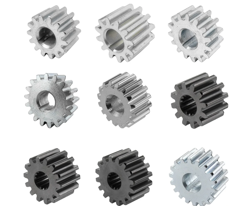
1. Dynamics Modeling of the Gear Transmission System
I use the lumped mass method to model the gear transmission system. Each component is treated as a rigid mass connected by springs and dampers. For the spiral bevel pinion gears, I consider bending, torsion, and axial motion. The generalized coordinate vector for the spiral bevel pinion gear pair is
$$ \mathbf{q}_{pg} = [x_p, y_p, z_p, \theta_{xp}, x_g, y_g, z_g, \theta_{zg}]^T $$
Here p denotes the small pinion and g denotes the large gear. The relative displacement along the mesh line is
$$ \delta_{12}(t) = a_1 (x_p – x_g) + a_2 (y_p – y_g) + a_3 (z_p – z_g) + (r_p \theta_p – r_g \theta_g) – e_m(t) $$
The coefficients depend on the normal pressure angle, the spiral angle, and the pitch cone angle. They are given by
$$ a_1 = \sin\alpha_n \cos\delta + \cos\alpha_n \sin\beta \sin\delta $$
$$ a_2 = \sin\alpha_n \sin\delta – \cos\alpha_n \sin\beta \cos\delta $$
$$ a_3 = \cos\alpha_n \cos\beta $$
The normal dynamic mesh force is
$$ F_n = k_m(t) \delta_{12}(t) + c_m \dot{\delta}_{12}(t) $$
The force components along the x, y, and z axes are
$$ F_x = F_n a_1, \quad F_y = F_n a_2, \quad F_z = F_n a_3 $$
I write the equations of motion for the pinion and the gear as
$$ m_p \ddot{x}_p + c_{px} \dot{x}_p + k_{px} x_p = -F_x $$
$$ m_p \ddot{y}_p + c_{py} \dot{y}_p + k_{py} y_p = -F_y $$
$$ m_p \ddot{z}_p + c_{pz} \dot{z}_p + k_{pz} z_p = -F_z $$
$$ I_{xp} \ddot{\theta}_{xp} = T_1 – F_n r_p $$
$$ m_g \ddot{x}_g + c_{gx} \dot{x}_g + k_{gx} x_g = F_x $$
$$ m_g \ddot{y}_g + c_{gy} \dot{y}_g + k_{gy} y_g = F_y $$
$$ m_g \ddot{z}_g + c_{gz} \dot{z}_g + k_{gz} z_g = F_z $$
$$ I_{zg} \ddot{\theta}_{zg} = -T_2 + F_n r_g $$
For the planetary gear train, I model the sun, the ring, the carrier, and three planets. Each planet has two translational and one rotational degree of freedom. The mesh displacements are
$$ \delta_{sn} = \mathbf{V}_{sn} \mathbf{q}_{sn} – e_{sn}(t) $$
$$ \delta_{rn} = \mathbf{V}_{rn} \mathbf{q}_{rn} – e_{rn}(t) $$
The projection vectors are
$$ \mathbf{V}_{sn} = [\sin\theta_{sn}, \cos\theta_{sn}, 1, -\sin\alpha, -\cos\alpha, -1] $$
$$ \mathbf{V}_{rn} = [\sin\theta_{rn}, \cos\theta_{rn}, 1, \sin\alpha, \cos\alpha, -1] $$
The equations of motion for the sun, planet, ring, and carrier are
$$ m_s \ddot{x}_s + k_{sx} x_s + \sum_{i=1}^{3} k_{sn} \delta_{sni} \sin\theta_{sni} = 0 $$
$$ m_s \ddot{y}_s + k_{sy} y_s + \sum_{i=1}^{3} k_{sn} \delta_{sni} \cos\theta_{sni} = 0 $$
$$ \frac{I_s}{r_s^2} \ddot{u}_s + k_{su} u_s + \sum_{i=1}^{3} k_{sn} \delta_{sni} = \frac{T_{ps}}{r_s} $$
$$ m_n \ddot{x}_{ni} + k_{cn} \delta_{cnxi} – k_{sn} \delta_{sni} \sin\alpha + k_{rn} \delta_{rni} \sin\alpha = 0 $$
$$ m_n \ddot{y}_{ni} + k_{cn} \delta_{cnyi} – k_{sn} \delta_{sni} \cos\alpha – k_{rn} \delta_{rni} \cos\alpha = 0 $$
$$ \frac{I_n}{r_n^2} \ddot{u}_{ni} – k_{rn} \delta_{rni} + k_{sn} \delta_{sni} = 0 $$
$$ m_r \ddot{x}_r + k_{rx} x_r + \sum_{i=1}^{3} k_{rn} \delta_{rni} \sin\theta_{rni} = 0 $$
$$ m_r \ddot{y}_r + k_{ry} y_r + \sum_{i=1}^{3} k_{rn} \delta_{rni} \cos\theta_{rni} = 0 $$
$$ \frac{I_r}{r_r^2} \ddot{u}_r + k_{ru} u_r + \sum_{i=1}^{3} k_{rn} \delta_{rni} = 0 $$
$$ m_c \ddot{x}_c + k_{cx} x_c + \sum_{i=1}^{3} k_{cn} (\delta_{cnxi} \cos\theta_{ni} + \delta_{cnyi} \sin\theta_{ni}) = 0 $$
$$ m_c \ddot{y}_c + k_{cy} y_c + \sum_{i=1}^{3} k_{cn} (\delta_{cnxi} \sin\theta_{ni} – \delta_{cnyi} \cos\theta_{ni}) = 0 $$
$$ \frac{I_c}{r_c^2} \ddot{u}_c + k_{cu} u_c + \sum_{i=1}^{3} k_{cn} \delta_{cnyi} = \frac{T_L}{r_c} $$
I compute the time-varying mesh stiffness using a gear design tool. Table 1 lists the gear parameters. Table 2 lists the natural frequencies and mesh frequencies.
| Parameter | Small Bevel Pinion | Large Bevel Gear | Sun | Planet | Ring | Carrier |
|---|---|---|---|---|---|---|
| Module | 10.85 | 10.85 | 4.5 | 4.5 | 4.5 | — |
| Number of teeth | 16 | 57 | 23 | 35 | 93 | — |
| Pressure angle (°) | 20 | 20 | 20 | 20 | 20 | — |
| Spiral angle (°) | 30 | 30 | 0 | 0 | 0 | — |
| Mass (kg) | 2.14 | 118.73 | 7.38 | 5.20 | 36.71 | 242.75 |
| Inertia (kg·m²) | 0.16 | 5.41 | 0.01 | 0.29 | 1.83 | 7.03 |
| Support stiffness (N·m) | 2×10⁹ | 2×10⁹ | 1.18×10⁹ | 5×10⁷ | 7.38×10⁹ | 8.63×10⁸ |
| Torsional stiffness (N·m) | 2.9×10⁹ | 2.9×10⁹ | 3.47×10⁹ | — | 83.40×10⁹ | 3.64×10⁸ |
| Location | First frequency (Hz) | Second frequency (Hz) | Third frequency (Hz) |
|---|---|---|---|
| Motor rotor | 50 | 100 | 150 |
| Motor stator | 50 | 180 | 360 |
| High-speed shaft | 5 | 10 | 15 |
| Bevel pinion mesh | 60 | 120 | 180 |
| Second shaft | 1.5 | 2.9 | 4.4 |
| Planetary mesh | 25.3 | 50.6 | 75.8 |
The dynamic transmission error is
$$ \mathrm{DTE} = \mathbf{V} \mathbf{q} $$
The dynamic mesh force is
$$ F = k(t) \delta(t) $$
2. Dynamic Response Analysis
I solve the equations using the Newmark method. The integration parameters are α and β. The updating formulas are
$$ \dot{x}_{t+\Delta t} = \dot{x}_t + [(1-\beta)\ddot{x}_t + \beta \ddot{x}_{t+\Delta t}] \Delta t $$
$$ x_{t+\Delta t} = x_t + \dot{x}_t \Delta t + \left[ \left(\frac{1}{2}-\alpha\right)\ddot{x}_t + \alpha \ddot{x}_{t+\Delta t} \right] \Delta t^2 $$
The effective stiffness and load are
$$ K_{\mathrm{eff}} = K + A_1 M + A_2 C $$
$$ F_{\mathrm{eff}} = F_{t+\Delta t} + M(A_1 x_t + A_3 \dot{x}_t + A_4 \ddot{x}_t) + C(A_2 x_t + A_5 \dot{x}_t + A_6 \ddot{x}_t) $$
The integration constants are
$$ A_1 = \frac{1}{\alpha \Delta t^2}, \quad A_2 = \frac{\beta}{\alpha \Delta t}, \quad A_3 = \frac{1}{\alpha \Delta t} $$
$$ A_4 = \frac{1}{2\alpha} – 1, \quad A_5 = \frac{\beta}{\alpha} – 1, \quad A_6 = \frac{\Delta t}{2} \left( \frac{\beta}{\alpha} – 2 \right) $$
I analyze the dynamic transmission error and mesh force. The results show that the spiral bevel pinion gears have larger dynamic transmission error than the planetary gears because they rotate faster. The planetary gears carry higher torque, so their mesh forces are larger. Table 3 shows the mesh force statistics for each gear pair. The pinion gear mesh force has a mean value near 38.43 kN. The planetary external mesh force has a mean value near 85.47 kN. The planetary internal mesh force has a mean value near 85.46 kN.
| Gear pair | Maximum force (kN) | Fluctuation (kN) | Mean force (kN) |
|---|---|---|---|
| Spiral bevel pinion gears | 38.49 | 0.12 | 38.43 |
| Sun–planet 1 external | 87.58 | 4.12 | 85.47 |
| Sun–planet 2 external | 87.48 | 4.42 | 85.32 |
| Sun–planet 3 external | 87.67 | 4.51 | 85.55 |
| Ring–planet 1 internal | 87.61 | 4.24 | 85.46 |
| Ring–planet 2 internal | 87.60 | 4.40 | 85.54 |
| Ring–planet 3 internal | 87.71 | 4.49 | 85.54 |
I study the effect of input speed. I keep the power constant and change the speed. Table 4 shows the maximum mesh force for different speeds. The mesh force decreases as speed increases because the torque decreases. For low-speed heavy-duty systems, the pinion gears experience higher mesh force.
| Input speed (r/min) | Maximum external mesh force (kN) |
|---|---|
| 280 | 101.20 |
| 290 | 97.80 |
| 300 | 94.63 |
| 310 | 91.65 |
| 320 | 88.87 |
I also study the effect of input power. Table 5 shows the maximum mesh force for different powers. The mesh force increases with power. The trend is more significant for low-speed heavy-duty operation.
| Input power (kW) | Maximum external mesh force (kN) |
|---|---|
| 180 | 70.54 |
| 190 | 79.58 |
| 200 | 87.58 |
| 210 | 96.81 |
| 220 | 104.94 |
3. Electromagnetic Simulation of the Permanent Magnet Synchronous Motor
I build a finite element model of a 20-pole, 72-slot permanent magnet synchronous motor. The motor parameters are in Table 6. I analyze no-load back electromotive force, electromagnetic force, cogging torque, torque ripple, and efficiency. The pinion gears are driven by this motor, so the electromagnetic torque ripple directly affects the pinion gear mesh.
| Parameter | Value | Parameter | Value | Parameter | Value |
|---|---|---|---|---|---|
| Poles / slots | 20 / 72 | Slot opening width (mm) | 3.5 | d-axis inductance (H) | 0.135 |
| Stator outer diameter (mm) | 720 | Number of phases | 3 | q-axis inductance (H) | 0.329 |
| Stator inner diameter (mm) | 510 | Winding connection | Star | Inertia (kg·m²) | 9.5 |
| Core length (mm) | 640 | Tooth width (mm) | 13.1 | Flux linkage (H) | 25.4 |
| Motor length (mm) | 1100 | Air gap length (mm) | 1.9 | Stator resistance (Ω) | 111.7 |
| Cooling | Water | Permanent magnet | N38UH | Magnet length (mm) | 640 |
The stator magnetomotive force is
$$ f_A(\theta,t) = \sum_{v} f_v \cos(v\theta – \omega t) $$
The rotor magnetomotive force is
$$ f_R(\theta,t) = \sum_{\mu} f_{\mu} \cos(\mu\theta – \omega t / p_n) $$
The air-gap permeance is
$$ \lambda_g(\theta) = \lambda_0 + \sum_{k=1}^{\infty} \lambda_k \cos(k z \theta) $$
The radial flux density is
$$ B_r(\theta,t) = [f_A(\theta,t) + f_R(\theta,t)] \lambda_g(\theta) $$
The electromagnetic force is
$$ P(\theta,t) = \frac{1}{2\mu_0} [B_r^2(\theta,t) – B_t^2(\theta,t)] $$
The no-load back electromotive force is nearly sinusoidal with an amplitude of 257.84 V. The main harmonics are the first and third. The radial electromagnetic force has a dominant 20th harmonic with amplitude 0.3075 kN at no load and 0.3086 kN at load. The tangential force is much smaller. Table 7 shows the main force harmonics.
| Harmonic order | Radial force at no load (kN) | Radial force at load (kN) | Tangential force at load (kN) |
|---|---|---|---|
| 20 | 0.3075 | 0.3086 | — |
| 32 | 0.0450 | 0.0460 | 0.0120 |
| 40 | 0.0520 | 0.0557 | 0.0150 |
| 52 | 0.0380 | 0.0390 | 0.0100 |
| 80 | 0.0800 | 0.0821 | 0.0200 |
| 100 | 0.0540 | 0.0557 | 0.0180 |
| 140 | 0.0680 | 0.0698 | 0.0351 |
I analyze the effect of slot opening width. Table 8 shows the maximum radial force for different slot opening widths. The radial force increases with slot opening. I also analyze the effect of air gap length. Table 9 shows that radial force decreases as air gap length increases.
| Slot opening width (mm) | Maximum radial force (kN) |
|---|---|
| 2.5 | 0.7308 |
| 3.0 | 0.7451 |
| 3.5 | 0.7694 |
| 4.0 | 0.7730 |
| 4.5 | 0.8032 |
| 5.0 | 0.8213 |
| Air gap length (mm) | Maximum radial force (kN) |
|---|---|
| 1.5 | 0.8626 |
| 1.6 | 0.8333 |
| 1.7 | 0.8130 |
| 1.8 | 0.7847 |
| 1.9 | 0.7694 |
| 2.0 | 0.7610 |
I analyze cogging torque. The maximum cogging torque is 0.1318 N·m for the 20-pole 72-slot design. Table 10 shows the effect of pole-slot combinations. Increasing the slot number reduces cogging torque but increases size. Table 11 shows the effect of slot opening width. The cogging torque first decreases and then increases. I select a slot opening of 3.5 mm for the final design.
| Pole–slot combination | Maximum cogging torque (N·m) |
|---|---|
| 20 poles, 48 slots | 5.2745 |
| 20 poles, 60 slots | 2.2450 |
| 20 poles, 72 slots | 0.1318 |
| 20 poles, 84 slots | 0.0890 |
| 20 poles, 96 slots | 0.0667 |
| Slot opening width (mm) | Maximum cogging torque (N·m) |
|---|---|
| 2.5 | 0.2461 |
| 3.0 | 0.2137 |
| 3.5 | 0.1318 |
| 4.0 | 0.1500 |
| 4.5 | 0.1569 |
| 5.0 | 0.1599 |
I also analyze torque ripple and efficiency. The output torque is about 6600 N·m up to 300 r/min. The torque ripple is small. The efficiency reaches about 98% after 50 r/min. The pinion gears receive a smooth torque from the motor when the torque ripple is low.
4. Electromechanical Coupling Dynamics
I combine the permanent magnet synchronous motor model with the gear transmission model. The motor equations in the dq frame are
$$ u_d = R_s i_d + L_d \frac{di_d}{dt} – \omega_e L_q i_q $$
$$ u_q = R_s i_q + L_q \frac{di_q}{dt} + \omega_e (L_d i_d + \psi_f) $$
$$ T_e = \frac{3}{2} p_n [ \psi_f i_q + (L_d – L_q) i_d i_q ] $$
$$ J_m \frac{d\omega_m}{dt} = T_e – T_m $$
The coupling equation for the motor and the first pinion gear is
$$ T_m = k_u (u_{in} – u_{1}) $$
I use vector control with \(i_d = 0\). The q-axis current reference is generated by a sliding mode speed controller. The sliding surface is
$$ s = c x_1 + x_2 $$
$$ x_1 = \omega_r – \omega_m, \quad x_2 = \dot{x}_1 $$
The control law is
$$ i_q^* = \frac{1}{D} \int_0^t [c x_2 + \varepsilon \operatorname{sgn}(s) + q s] d\tau $$
I use a model reference adaptive system to estimate speed and rotor position. The adaptive law is
$$ \hat{\omega}_e = K_p (i_d’ \hat{i}_q’ – i_q’ \hat{i}_d’) + K_i \int (i_d’ \hat{i}_q’ – i_q’ \hat{i}_d’) dt $$
I build the simulation model. The motor speed reaches 300 r/min in about 1 s. The three-phase current has an amplitude near 50 A. The dynamic transmission error and mesh force are larger after coupling. Table 12 shows the mesh force comparison before and after coupling. The pinion gears experience a higher mesh force after coupling because the electromechanical interaction adds harmonics.
| Gear pair | Maximum force before coupling (kN) | Maximum force after coupling (kN) | Mean force after coupling (kN) |
|---|---|---|---|
| Spiral bevel pinion gears | 38.49 | 38.56 | 38.51 |
| Sun–planet 1 external | 87.58 | 94.40 | 83.51 |
| Ring–planet 1 internal | 87.61 | 92.92 | 83.25 |
I analyze three load conditions: constant load, fluctuating load, and sudden load. Table 13 summarizes the results. Under fluctuating load, the mesh force follows the load. Under sudden load, the mesh force changes abruptly. The coupled system contains additional frequencies, including electromechanical harmonic frequencies. The pinion gears show a strong response to these additional frequencies.
| Load condition | Maximum external mesh force (kN) | Frequency content |
|---|---|---|
| Constant load | 94.40 | Mesh frequencies and multiples |
| Fluctuating load | 112.30 | Mesh frequencies, load fluctuation frequency |
| Sudden load | 128.70 | Broadband, electromechanical harmonics |
5. Experimental Study
I build a test bench for the permanent magnet motor and pinion gear drive system. The test bench includes the drive system, couplings, torque sensor, and a 390 kW motor for loading. I use a B&K vibration measurement system. I place four measurement points: at the motor-gearbox connection, above the large bevel pinion gear bearing, above the ring gear, and at the motor tail. I perform no-load and load tests at 25%, 50%, 70%, 100%, and 130% rated torque. Table 14 lists the test equipment.
| Equipment | Model | Equipment | Model |
|---|---|---|---|
| Motor | TYCPT 400S-20 | Universal coupling | SWC285 |
| Torque sensor | JN338-20000 | Base | BGGS280 |
| Data acquisition | HB6008-G | High-speed coupling | NGGS280-03T |
| Vibration system | B&K system | Speed sensor | B&K sensor |
The vibration spectra show peaks near 25 Hz, 60 Hz, and 100 Hz. These correspond to the mesh frequencies and their multiples. The motor tail vibration is mainly caused by electromagnetic forces. The pinion gear location shows combined motor and gear excitation. The planetary gear location is dominated by the planetary mesh frequency and the second harmonic of the spiral bevel pinion gears. Table 15 compares the experimental and simulated peaks. The maximum error is 9.81%, and the average error is 6.27%.
| Measurement point | Experimental peak (μm/s) | Simulated peak (μm/s) | Error (%) |
|---|---|---|---|
| Point 1: motor-gearbox connection | 353.89 | 373.20 | 5.46 |
| Point 2: above large bevel pinion gear bearing | 514.26 | 533.80 | 3.80 |
| Point 3: above ring gear | 240.03 | 263.58 | 9.81 |
| Point 4: motor tail | 340.26 | 360.73 | 6.02 |
6. Conclusions
I have established a dynamic model of a permanent magnet motor and pinion gear drive system. The model includes spiral bevel pinion gears and a planetary gear train. I used the lumped mass method with time-varying mesh stiffness and comprehensive mesh error. I solved the equations with the Newmark method. The mesh force decreases with speed and increases with power. For low-speed heavy-duty systems, the pinion gears experience high mesh force.
I built a finite element model of a 20-pole 72-slot permanent magnet synchronous motor. The radial electromagnetic force is larger than the tangential force. The radial force increases with slot opening width and decreases with air gap length. The cogging torque decreases with slot number and has a minimum with respect to slot opening width. I selected a 3.5 mm slot opening.
I developed an electromechanical coupling model. The coupling introduces additional harmonics. The mesh force increases after coupling. Under fluctuating and sudden loads, the mesh force peaks are higher. I used sliding mode control and model reference adaptive system control for robust operation. The pinion gears are the most sensitive components to electromechanical coupling because they are close to the motor and operate at high speed.
I validated the model with experiments. The simulated and measured vibration spectra agree well. The maximum error is below 10%. The results provide a basis for dynamic optimization of permanent magnet motor and pinion gear drive systems. Future work should include more detailed tooth contact analysis of the pinion gears, rotor eccentricity, and additional electromechanical factors.