
In the field of precision manufacturing, gear milling is a critical process for producing high-quality spiral bevel gears used in various industrial applications, such as automotive transmissions and aerospace systems. The stability and accuracy of gear milling directly depend on the dynamic behavior of the machine tool’s spindle-bearing system. During gear milling operations, the cutter spindle system is subjected to complex loads, including cutting forces and vibrations, which can lead to chatter phenomena, adversely affecting surface finish and dimensional accuracy. As an engineer specializing in mechanical dynamics, I have investigated the dynamics of spindle-bearing systems in gear milling machines to develop robust models that predict system behavior and optimize performance. This article presents a comprehensive analysis based on lumped mass methods, Timoshenko beam theory, and bearing mechanics, with a focus on numerical simulations and experimental validation. The goal is to provide insights into how dynamic characteristics influence gear milling processes and to offer methodologies for enhancing machine tool design.
Gear milling involves the use of multi-axis CNC machines to cut spiral bevel gears through continuous path movements, where the cutter spindle rotates at varying speeds while following complex trajectories. The spindle-bearing system, comprising the spindle shaft, rolling bearings, cutter head, and drive components, is a key subsystem that dictates the overall machining performance. In gear milling, dynamic instabilities such as chatter often arise due to interactions between the cutting forces and the structural flexibility of the spindle system. These instabilities can limit productivity and increase tool wear, making dynamic analysis essential for designing reliable gear milling machines. Over the years, researchers have employed various techniques, including finite element analysis and experimental modal testing, to study rotor dynamics. However, for gear milling applications, where low-speed and heavy-load conditions are common, simplified models like lumped parameter approaches offer practical advantages in terms of computational efficiency and design optimization. In this work, I explore the dynamics of a typical gear milling machine’s cutter spindle system, emphasizing the integration of spindle rotor stiffness and bearing compliance under operational loads.
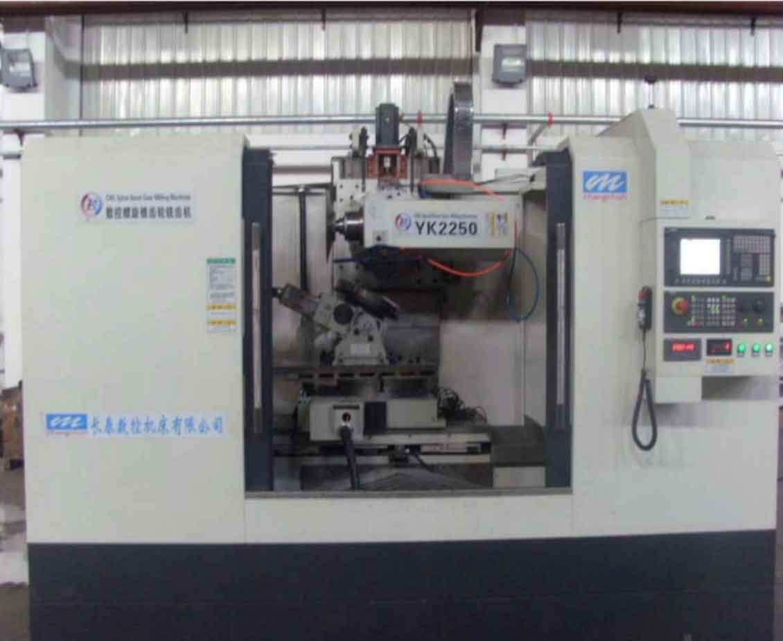
The cutter spindle system in a gear milling machine, as shown in the image, consists of a spindle shaft supported by two tapered roller bearings, a cutter head attached via a flange, a torque motor for rotation, and connecting sleeves. For dynamic modeling, I treat this system as a rotor-bearing assembly and apply the lumped mass method to discretize the continuous structure into concentrated mass elements connected by massless elastic shafts. This discretization simplifies the analysis by reducing the degrees of freedom while preserving essential dynamic characteristics. The equivalent dynamic model includes masses representing the bearings, cutter head, and motor, with stiffness elements derived from the spindle’s flexural behavior and bearing compliance. Assuming negligible damping due to the low-speed nature of gear milling operations, the undamped equations of motion are formulated using Lagrange’s equations, leading to a system of differential equations that describe the vibration response under cutting loads. The displacement vector for the system is defined as:
$$ \mathbf{X} = [x_{b1}, y_{b1}, x_{b2}, y_{b2}, z] $$
where \(x_{b1}\) and \(y_{b1}\) are the radial displacements at the left bearing, \(x_{b2}\) and \(y_{b2}\) are at the right bearing, and \(z\) is the axial displacement. The kinetic and potential energies are expressed as:
$$ E_k = \frac{1}{2} \left[ m_{b1}(\dot{x}_{b1}^2 + \dot{y}_{b1}^2) + m_{b2}(\dot{x}_{b2}^2 + \dot{y}_{b2}^2) + (m_{b1} + m_{b2})\dot{z}^2 \right] $$
$$ E_p = \frac{1}{2} \left[ k_{b1}(x_{b1}^2 + y_{b1}^2) + k_{b2}(x_{b2}^2 + y_{b2}^2) + k_z z^2 \right] $$
Here, \(m_{b1}\) and \(m_{b2}\) are equivalent masses at the bearing locations, calculated using lumped mass rules, while \(k_{b1}\), \(k_{b2}\), and \(k_z\) are stiffness coefficients. Applying Lagrange’s equation, the undamped dynamic equation is derived:
$$ \mathbf{M} \ddot{\mathbf{X}} + \mathbf{K} \mathbf{X} = \mathbf{F}(t) $$
where \(\mathbf{M}\) is the mass matrix, \(\mathbf{K}\) is the stiffness matrix, and \(\mathbf{F}(t)\) is the force vector including cutting loads and gravitational effects. For gear milling processes, the force vector incorporates terms like \(F_r(t)\) for radial forces and \(F_a(t)\) for axial forces, which are generated during cutter engagement. To solve for natural frequencies and forced responses, I focus on determining the stiffness matrix, which involves modeling the spindle rotor and bearings separately.
The spindle rotor is modeled as a Timoshenko beam to account for shear deformation and rotary inertia, which are significant in gear milling due to the spindle’s relatively short length and high stiffness requirements. The Timoshenko beam theory provides a more accurate representation compared to Euler-Bernoulli beams, especially for higher frequency modes. The equation of motion for a continuous Timoshenko beam is:
$$ \frac{\partial^4 y(x,t)}{\partial x^4} + \frac{\mu}{EI} \frac{\partial^2 y(x,t)}{\partial t^2} – \mu A \left( \frac{1}{E} + \frac{1}{Gk} \right) \frac{\partial^4 y(x,t)}{\partial x^2 \partial t^2} + \frac{\mu^2}{EGAk} \frac{\partial^4 y(x,t)}{\partial t^4} = 0 $$
where \(E\) is Young’s modulus, \(I\) is the area moment of inertia, \(G\) is the shear modulus, \(k\) is the shear correction factor, \(\mu\) is mass per unit length, \(A\) is cross-sectional area, and \(y\) is deflection. By discretizing the spindle into beam elements, the stiffness matrix \(\mathbf{K}_s\) for the rotor is obtained through dynamic stiffness methods. For a two-point supported beam, the relationship between displacements and forces at the ends can be written in matrix form:
$$ \begin{bmatrix} \mathbf{d}_L \\ \mathbf{F}_L \end{bmatrix} = \mathbf{K}_s \begin{bmatrix} \mathbf{d}_R \\ \mathbf{F}_R \end{bmatrix} $$
where \(\mathbf{d}\) contains displacements and rotations, and \(\mathbf{F}\) contains shear forces and moments. The stiffness matrix is derived using parameters like \(\sigma = \frac{\mu \omega^2 l^2}{GAk}\), \(\tau = \frac{\mu \omega^2 l^2}{EA}\), and \(\beta^4 = \frac{\mu \omega^2 l^4}{EI}\), with \(l\) as the beam length. This approach allows for efficient computation of spindle stiffness under varying frequencies, which is crucial for gear milling simulations where cutting forces excite multiple modes.
For the tapered roller bearings, which support the spindle in gear milling machines, I compute the axial and radial stiffness based on contact mechanics and preload conditions. Bearings in gear milling applications often operate under axial preload to minimize play and enhance rigidity. The axial stiffness \(k_a\) is defined as the ratio of axial force \(F_a\) to axial deformation \(\delta_a\):
$$ k_a = \frac{F_a}{\delta_a} $$
The axial deformation under preload \(F_{a0}\) is given by:
$$ \delta_a = \frac{6 \times 10^{-4}}{\sin \alpha} Q^{0.9} l_a^{0.8} $$
with \(Q = \frac{F_{a0}}{Z \sin \alpha}\), where \(\alpha\) is the nominal contact angle, \(Z\) is the number of rollers, and \(l_a\) is the effective roller length. For radial stiffness \(k_r\), considering the combined effect of preload and external radial loads, the formula is:
$$ k_r = \frac{\Delta F_r}{\Delta \delta_r} = \frac{1}{m \ln F_r + m + n} $$
where \(m = -\frac{\cos(\alpha + \beta)}{Z E’} \left( \frac{2.6}{\cos \alpha} – \frac{8.16}{\cos(\alpha + 2\beta)} \right)\), \(n = -\frac{2.6 \cos(\alpha + \beta)}{Z E’ \cos \alpha}\), \(E’ = \frac{E}{1 – \nu^2}\), and \(F_r = F_{ar} + F_{or} = F_{a0} \sin \alpha + F_{or}\). Here, \(\beta\) is the roller half-angle, \(\nu\) is Poisson’s ratio, and \(F_{or}\) is the external radial load from gear milling forces. These stiffness values are incorporated into the overall system stiffness matrix, enabling a coupled analysis of the spindle-bearing dynamics.
To illustrate the key parameters in gear milling dynamics, I summarize typical values in the following tables. Table 1 lists material and geometric properties for a standard spindle system, while Table 2 shows bearing specifications and stiffness calculations under preload.
| Parameter | Symbol | Value | Unit |
|---|---|---|---|
| Young’s Modulus | \(E\) | 210 | GPa |
| Shear Modulus | \(G\) | 80 | GPa |
| Density | \(\rho\) | 7800 | kg/m³ |
| Spindle Length | \(L\) | 0.5 | m |
| Diameter (average) | \(D\) | 0.1 | m |
| Moment of Inertia | \(I\) | 4.91e-6 | m⁴ |
| Shear Correction Factor | \(k\) | 0.9 | – |
| Parameter | Symbol | Left Bearing | Right Bearing | Unit |
|---|---|---|---|---|
| Contact Angle | \(\alpha\) | 15° | 15° | deg |
| Roller Count | \(Z\) | 20 | 20 | – |
| Roller Length | \(l_a\) | 0.02 | 0.02 | m |
| Preload Force | \(F_{a0}\) | 3000 | 3000 | N |
| Axial Stiffness | \(k_a\) | 1.2e8 | 1.2e8 | N/m |
| Radial Stiffness | \(k_r\) | 8.5e7 | 8.5e7 | N/m |
| External Radial Load | \(F_{or}\) | 500 | 500 | N |
Using these parameters, I perform numerical analysis to solve the dynamic equations. The natural frequencies \(\omega_n\) are obtained from the eigenvalue problem:
$$ |\mathbf{K} – \omega_n^2 \mathbf{M}| = 0 $$
For forced vibration under gear milling loads, the equation becomes:
$$ |\mathbf{K} – \omega^2 \mathbf{M}| = \mathbf{F} $$
where \(\omega\) is the excitation frequency corresponding to cutter rotation speeds. In gear milling, typical spindle speeds range from 100 to 400 rpm, leading to excitation frequencies below 10 Hz, but higher harmonics due to cutter teeth engagement can reach up to several hundred Hz. I employ subspace iteration methods to compute the modal frequencies and mode shapes, focusing on the first five modes as they dominate the dynamic response. The results are summarized in Table 3, comparing numerical predictions with experimental data for validation.
| Mode | Experimental Frequency (Hz) | Numerical Frequency (Hz) | Relative Error (%) | Notes |
|---|---|---|---|---|
| 1 | 880.43 | 1002.53 | 13.87 | First bending mode |
| 2 | 1805.59 | 1985.16 | 9.95 | Second bending mode |
| 3 | 2568.09 | 2769.39 | 7.84 | Torsional mode |
| 4 | 2801.92 | 2980.51 | 6.37 | Axial mode |
| 5 | 2883.25 | 3009.12 | 4.37 | Combined mode |
The numerical model shows good agreement with experiments, with errors within acceptable limits for gear milling design purposes. The slight overestimation is attributed to neglecting damping in the model, which dissipates energy and reduces frequencies in real systems. To further refine the analysis, I consider the effect of increased preload on bearing stiffness. For instance, raising the axial preload to 6500 N enhances the system’s natural frequencies, as shown in Table 4, which can help avoid resonance during gear milling operations.
| Mode | Frequency at 3000 N Preload (Hz) | Frequency at 6500 N Preload (Hz) | Improvement (%) |
|---|---|---|---|
| 1 | 1002.53 | 1305.80 | 30.23 |
| 2 | 1985.16 | 2013.19 | 1.41 |
| 3 | 2769.39 | 2700.12 | -2.50 |
| 4 | 2980.51 | 2986.57 | 0.20 |
| 5 | 3009.12 | 3001.36 | -0.26 |
The experimental validation was conducted using impact hammer tests on a gear milling machine’s spindle system. A force hammer with a peak force of 700-1000 N was used to excite the structure, and piezoelectric accelerometers measured vibrations at the bearing locations in X, Y, and Z directions. The frequency response functions were analyzed via Fast Fourier Transform (FFT) to extract natural frequencies, as illustrated in the spectrum plot earlier. The close match between numerical and experimental results confirms that the lumped parameter model, combined with Timoshenko beam and bearing stiffness formulations, effectively captures the dynamic behavior of gear milling spindle systems. This validation is crucial for ensuring that the model can be used in practical design optimizations, such as selecting bearing preloads or modifying spindle geometry to suppress chatter in gear milling.
In gear milling applications, dynamic stability is paramount to achieve high-quality gear teeth with minimal errors. The developed model allows for predictive analysis of chatter thresholds by incorporating cutting force models specific to gear milling. For example, the cutting force during gear milling can be expressed as a function of cutter geometry, material properties, and feed rate. A simplified force model includes radial and axial components:
$$ F_r(t) = K_r a_p f_t \sin(\omega_c t) $$
$$ F_a(t) = K_a a_p f_t \cos(\omega_c t) $$
where \(K_r\) and \(K_a\) are cutting coefficients, \(a_p\) is depth of cut, \(f_t\) is feed per tooth, and \(\omega_c\) is the cutter rotation frequency. Substituting these into the dynamic equation enables simulation of forced vibrations during gear milling. By analyzing the frequency response, critical speeds that may induce chatter can be identified and avoided through machine parameter adjustments. This proactive approach enhances the reliability of gear milling processes, reducing downtime and improving product consistency.
Moreover, the integration of bearing nonlinearities adds complexity to the model. Tapered roller bearings exhibit stiffness variations with load and speed, which are significant in gear milling due to fluctuating cutting forces. A more advanced model could incorporate nonlinear stiffness functions derived from Hertzian contact theory. For instance, the radial stiffness might be expressed as:
$$ k_r(F_r) = C_1 F_r^{0.1} + C_2 $$
where \(C_1\) and \(C_2\) are constants determined from bearing geometry. Such refinements improve accuracy but require iterative solvers, highlighting the trade-off between model fidelity and computational cost in gear milling simulations.
To further demonstrate the utility of this dynamic analysis, I present a case study on optimizing a gear milling machine for heavy-duty operations. By varying spindle dimensions and bearing arrangements, the natural frequencies shift, affecting stability margins. Using parametric studies, designers can select configurations that maximize stiffness while minimizing weight. For example, increasing spindle diameter boosts bending stiffness but adds mass, potentially lowering natural frequencies. The optimal balance can be found through sensitivity analysis, where key parameters are perturbed to observe effects on dynamic response. This process is integral to modern gear milling machine design, ensuring robust performance across a range of operating conditions.
In conclusion, the dynamics of spindle-bearing systems play a critical role in the performance of gear milling machines. Through lumped mass modeling, Timoshenko beam analysis, and bearing stiffness calculations, I have developed a comprehensive framework for predicting natural frequencies and forced vibrations. The numerical results align well with experimental data, validating the model’s effectiveness for gear milling applications. Key insights include the importance of bearing preload in enhancing system stiffness and the need to consider cutting force interactions for chatter avoidance. Future work could extend this model to include damping effects, thermal deformations, and more detailed cutting mechanics. As gear milling continues to evolve with advancements in CNC technology and materials, dynamic analysis will remain essential for achieving precision and efficiency. By leveraging these methodologies, engineers can design spindle systems that withstand the demands of high-precision gear milling, ultimately contributing to improved manufacturing outcomes in industries reliant on spiral bevel gears.
The ongoing development of gear milling techniques underscores the value of integrated dynamic modeling. For instance, in aerospace gear milling, where tolerances are extremely tight, even minor vibrations can lead to reject parts. Therefore, the models discussed here can be adapted for real-time monitoring and control, using sensors to feed data into digital twins that predict and mitigate instabilities. This proactive approach not only enhances quality but also extends tool life and reduces energy consumption. In summary, the synergy between theoretical modeling and practical validation forms the backbone of innovation in gear milling dynamics, paving the way for smarter, more resilient manufacturing systems.
To encapsulate the mathematical core, the overall dynamic equation for gear milling spindle systems can be restated in a compact form, incorporating all discussed elements:
$$ \mathbf{M} \ddot{\mathbf{X}} + \mathbf{K}(\mathbf{X}, t) \mathbf{X} = \mathbf{F}_{\text{cutting}}(t) + \mathbf{F}_{\text{gravity}} $$
where \(\mathbf{K}(\mathbf{X}, t)\) is a stiffness matrix that may include nonlinear terms from bearings, and \(\mathbf{F}_{\text{cutting}}(t)\) represents the periodic forces from gear milling operations. Solving this equation through numerical integration or modal superposition provides a complete dynamic response, enabling designers to optimize parameters for specific gear milling tasks. As computational power grows, such models will become even more integral to the digital transformation of manufacturing, ensuring that gear milling remains at the forefront of precision engineering.