
The analysis of dynamic characteristics, particularly modal properties, is paramount in the design and reliability assessment of power transmission components. Among these, spiral bevel gears are indispensable in applications demanding high power density and efficiency in non-parallel shaft configurations, such as in aerospace propulsion systems, heavy-duty vehicle differentials, and precision industrial machinery. Their complex three-dimensional geometry and loaded tooth contact present unique challenges for dynamic analysis. Traditional modal analyses often constrain all degrees of freedom at the mounting interfaces, which, while informative for stationary components, fails to capture the critical effects induced by operational rotation. This investigation focuses explicitly on the dynamic modal behavior of a spiral bevel gear under high-speed conditions, where inertial forces significantly alter the system’s stiffness and vibrational characteristics. By employing a coupled parametric modeling and finite element analysis (FEA) approach, this work elucidates the profound impact of rotational speed on the natural frequencies and mode shapes of a spiral bevel gear, providing essential insights for avoiding resonant conditions and ensuring operational integrity in high-performance applications.
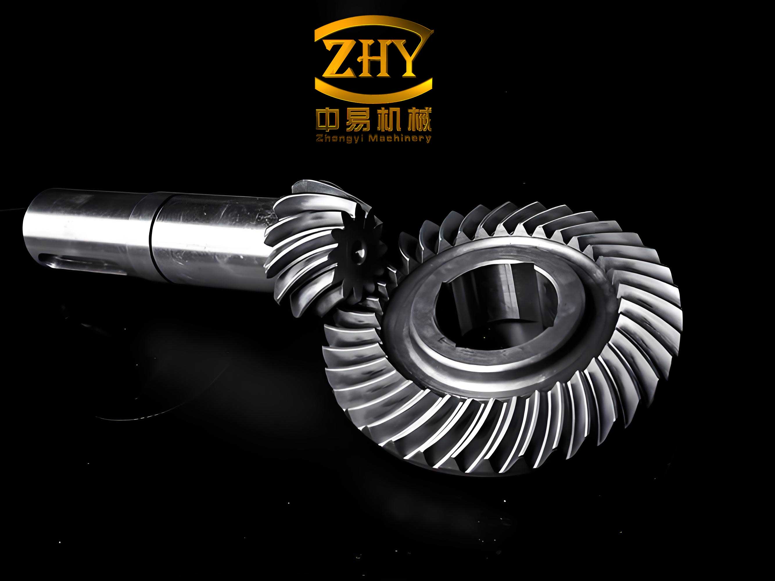
The foundational step for any accurate finite element analysis is the creation of a precise geometric model. The complex, spatially curved tooth form of a spiral bevel gear is generated based on the principles of gear generation, closely simulating the physical cutting process. The mathematical definition stems from the spherical involute curve, which can be parameterized. For a spiral bevel gear, the tooth surface coordinates are derived through a series of coordinate transformations involving the machine tool settings. A simplified representation of the surface generation relies on key geometric parameters. The basic geometric relationship for the pitch cone distance $R$ is given by:
$$ R = \frac{m_n Z_1}{2 \sin \gamma_1} = \frac{m_n Z_2}{2 \sin \gamma_2} $$
where $m_n$ is the normal module, $Z_1$ and $Z_2$ are the numbers of teeth for the pinion and gear respectively, and $\gamma_1$ and $\gamma_2$ are the pitch cone angles. The spiral angle $\beta$ at the mean cone distance is a critical parameter defining the curvature of the teeth. Using these parameters, a three-dimensional parametric model was developed in a CAD environment, allowing for easy modification of key design variables. The primary parameters for the subject spiral bevel gear (pinion) in this study are summarized in the table below.
| Parameter | Value | Parameter | Value |
|---|---|---|---|
| Material | 20CrMnTi Alloy Steel | Pressure Angle, $\alpha$ | 20° |
| Power Transmission, $P$ | 60 kW | Spiral Angle, $\beta$ | 35° |
| Pinion Speed, $N$ | 1000 – 10000 rpm | Profile Shift Coefficient, $X$ | 0 |
| Pinion Teeth, $Z_1$ | 22 | Addendum Coefficient, $h_a^*$ | 0.85 |
| Gear Teeth, $Z_2$ | 55 | Dedendum Coefficient, $h_f^*$ | 0.188 |
| Normal Module, $m_n$ | 9.2 mm |
The material properties for the alloy steel are essential inputs for the finite element model. The relevant mechanical properties are: Elastic Modulus, $E = 2.07 \times 10^{11}$ Pa; Poisson’s Ratio, $\nu = 0.25$; and Density, $\rho = 7.86 \times 10^{3}$ kg/m³. The CAD model was exported in a neutral format and imported into the ANSYS finite element software suite for subsequent analysis. The finite element discretization employed SOLID185 elements, an 8-node brick element suitable for 3-D modeling of solid structures. A combination of tetrahedral and hexahedral meshing was applied to balance computational accuracy and resource requirements, with a finer mesh applied to the critical tooth contact regions to capture stress gradients and deformation accurately. The boundary conditions for the modal analysis must reflect the operational mounting. The spiral bevel gear is assumed to be mounted on a rigid shaft. Therefore, all degrees of freedom (translational and rotational) for the nodes on the inner cylindrical surface of the gear bore are constrained, simulating a fixed connection to the shaft.
The core of this investigation involves a two-step analysis sequence: a static structural analysis followed by a prestressed modal analysis. The static analysis is performed not under external load, but under the influence of rotational velocity to compute the centrifugal stress field. When the spiral bevel gear rotates at a high angular velocity $\omega$, a radially outward centrifugal body force acts on every material point. The centrifugal force per unit volume at a radius $r$ is given by:
$$ F_c = \rho \omega^2 r $$
This force field induces a state of prestress within the gear body, causing radial expansion and tangential (hoop) stresses. This phenomenon is known as centrifugal stiffening or stress stiffening. The static analysis solves for the displacements and stresses resulting from this centrifugal load under the defined boundary conditions.
The second step, the prestressed modal analysis, calculates the natural frequencies and mode shapes of the spiral bevel gear while accounting for the stress-stiffness matrix derived from the static solution. The fundamental eigenvalue problem in FEA is:
$$ (-\omega_i^2 [M] + [K] + [S]) \{\phi_i\} = \{0\} $$
where $[M]$ is the mass matrix, $[K]$ is the elastic stiffness matrix, $[S]$ is the stress stiffness matrix (which is a function of the rotational speed $\omega$), $\omega_i$ is the i-th natural circular frequency, and $\{\phi_i\}$ is the corresponding mode shape vector. The stress stiffness matrix $[S]$ is positive for tensile stresses, effectively increasing the overall stiffness of the structure. Therefore, as rotational speed increases, the centrifugal tensile stresses increase $[S]$, leading to an increase in the system’s natural frequencies. This is in contrast to the effect of spin-softening, which is related to the weakening of the geometric stiffness due to the rotating coordinate system and is often negligible for solid structures like gears compared to the centrifugal stiffening effect. The Block Lanczos eigenvalue extraction method was utilized to solve for the first six natural frequencies and modes of the spiral bevel gear at various rotational speeds.
The results unequivocally demonstrate the significant influence of operational speed on the dynamic properties of the spiral bevel gear. The following table presents the first six natural frequencies (in Hz) extracted from the prestressed modal analysis at four distinct rotational speeds: 2000 rpm, 4000 rpm, 6000 rpm, and 10000 rpm.
| Mode Order | 2000 rpm | 4000 rpm | 6000 rpm | 10000 rpm |
|---|---|---|---|---|
| 1 | 4619.0 | 4623.0 | 4645.3 | 4699.1 |
| 2 | 6689.0 | 6692.4 | 6711.0 | 6773.0 |
| 3 | 6689.7 | 6693.0 | 6713.0 | 6775.5 |
| 4 | 7408.8 | 7412.9 | 7435.9 | 7497.0 |
| 5 | 9144.9 | 9149.0 | 9173.0 | 9237.6 |
| 6 | 9145.1 | 9149.3 | 9175.1 | 9239.0 |
The data reveals a clear and consistent trend: the natural frequencies of the spiral bevel gear increase monotonically with rotational speed. This is a direct consequence of the centrifugal stiffening effect. The increase is not linear but becomes more pronounced at higher speeds. For instance, the first natural frequency increases by approximately 4 Hz from 2000 to 4000 rpm (a 2000 rpm delta), but increases by nearly 54 Hz from 6000 to 10000 rpm (a 4000 rpm delta). This indicates that the stress stiffness matrix $[S]$ has a nonlinear dependence on the square of the rotational speed ($\omega^2$), as suggested by the centrifugal force formula. The phenomenon can be conceptually understood by considering the fundamental frequency equation for a simple system, $\omega_n = \sqrt{K_{eff}/M}$, where $K_{eff}$ is the effective stiffness. The centrifugal forces place the gear body in a state of tensile prestress, increasing $K_{eff}$ and thereby raising $\omega_n$, even though the mass $M$ remains constant.
Analyzing the mode shapes provides further insight into the dynamic behavior of the rotating spiral bevel gear. The first few modes typically involve global bending and torsion of the gear body. For a stationary gear, mode shapes are often degenerate (pairs with very close frequencies, like modes 2 & 3 and 5 & 6 in the table above) due to axisymmetry in the gear blank. Rotation breaks this symmetry slightly due to the presence of the teeth, but closely spaced pairs often remain. The prestress from rotation not only shifts the frequencies but can also slightly alter the deformation patterns compared to the stationary case. The dominant effect observed in the mode shapes at high speed is an underlying static deformation upon which the vibrational modes are superimposed. This static deformation field includes radial expansion and a slight twisting of the teeth due to the centrifugal pull. The displacement magnitude at specific points, such as along the tooth from the inner to the outer edge, shows a complex, non-uniform pattern that is modulated by the rotational speed, reflecting the interaction between the gear’s complex geometry and the centrifugal force field.
To quantify the stiffening effect, one can define a Frequency Shift Ratio $\eta_i$ for the i-th mode at a speed $\Omega$ relative to a near-stationary condition (e.g., 2000 rpm as a baseline):
$$ \eta_i(\Omega) = \frac{f_i(\Omega) – f_i(\Omega_{base})}{f_i(\Omega_{base})} \times 100\% $$
Calculating this for the first mode from the baseline of 2000 rpm to 10000 rpm yields:
$$ \eta_1(10000\text{ rpm}) = \frac{4699.1 – 4619.0}{4619.0} \times 100\% \approx 1.73\% $$
This shift, while seemingly small in percentage, is critically important in high-speed machinery where operational speeds may pass through or near resonant frequencies. A 1.73% shift could be sufficient to move a natural frequency away from a dangerous excitation harmonic, or conversely, into one. Therefore, neglecting this effect in the design phase could lead to unanticipated resonant vibrations, resulting in excessive noise, accelerated fatigue, or even catastrophic failure of the spiral bevel gear system.
The implications of this study are significant for the design and analysis of high-speed gearing systems. The demonstrated centrifugal stiffening effect must be incorporated into dynamic models for accurate prediction of critical speeds and resonant frequencies. This is especially crucial for spiral bevel gears used in applications like helicopter tail rotors or high-performance automotive differentials, where they operate at extreme rotational speeds. The parametric finite element methodology outlined here provides a robust framework for such analyses. Future work could extend this approach to include the effects of meshing stiffness variation, nonlinear contact under load, and the interaction between a pinion and gear pair in a full transmission dynamic analysis. Furthermore, investigating the combined effects of centrifugal stiffening and thermal gradients from power loss would yield an even more comprehensive understanding of spiral bevel gear dynamics in real-world operating environments.
In conclusion, this investigation has systematically analyzed the dynamic modal characteristics of a spiral bevel gear under the influence of high rotational speeds through advanced finite element techniques. The key finding is the confirmation and quantification of the centrifugal stiffening effect, which leads to a measurable and functionally important increase in the natural frequencies of the gear. This prestress-induced shift alters the fundamental dynamic signature of the component, moving its resonant peaks on a frequency map. For engineers designing and validating spiral bevel gear transmissions, this work underscores the necessity of performing prestressed modal analysis that accounts for operational rotation, rather than relying solely on conventional, stationary boundary condition analyses. Such a practice is essential for ensuring the reliable, quiet, and durable performance of these critical mechanical components across their entire operational envelope.