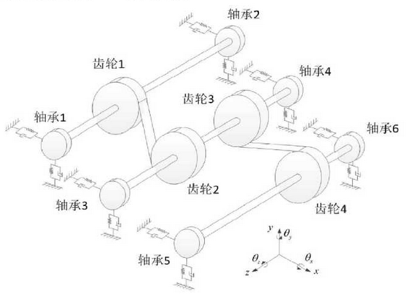
The bearings and gears are simplified as concentrated mass points and the rolling bearings are simplified as isotropic elastic supports.A simplified model of the two-stage fixed-shaft gear drive test device is shown in the figure and the two-stage gear drive parameters are shown in the table.Lagrange method is used to establish the yaw-torsion coupling nonlinear dynamic model of two-stage gear drive, in which there are 10 concentrated mass points and 50 degrees of freedom.

The kinetic energy function of the two-stage fixed-shaft gear drive system is:

In the formula, Tgi is the kinetic function of each gear, which is established by the method. The kinetic function of each gear pair is shown in the formula; Tbi is the kinetic function of each bearing:

Potential energy function of two-stage fixed-shaft gear drive system caused by elastic deformation of drive shaft and bearing is:

In this formula, Xi is the column vector composed of the generalized coordinates of each concentrated mass point on the ith drive shaft, Ki is the stiffness matrix of the ith drive shaft, Xbj is the column vector composed of the generalized coordinates of the jth bearing and Kbj is the stiffness matrix of the jth bearing.
Non-conservative generalized forces caused by gear engagement are determined by this method.By substituting kinetic energy function, potential energy function, energy dissipation function and non-conservative generalized force into Lagrange function, the yaw-torsion coupling non-linear dynamic equation of two-stage fixed-axle gear drive system can be obtained.
The dynamic equation of two-stage fixed-axle gear drive system is expressed as a matrix:

Nonlinear meshing force column vectors at the concentrated mass points of each gear can be obtained by analysis. As shown in the formula, the dynamic meshing force in the model is calculated using the non-linear dynamic meshing model proposed in Chapter 3.
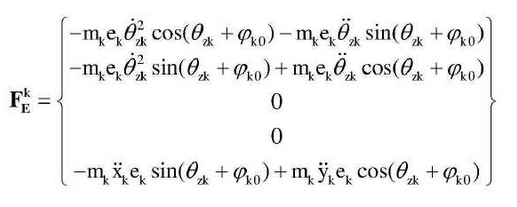
The vector of the non-linear inertial force column at the concentrated mass point of the k th gear is:

Where MK is the mass, EK is the eccentric, and_k0 is the initial angle of rotation for the position of the center of mass, and k=1,2,3,4 represents different gears.
The input torque and load torque corresponding to each test condition of gear drive system are respectively applied to the degree of torsional freedom of concentrated mass points of bearings 1 and 6, which is the external exciting load of the system.The theoretical rotational speed of each component under each test condition is taken as the initial condition of the torsional speed in the dynamic equation, and the 4-order Runge-Kutta method is used to simulate the equation.The numerical simulation results under different test conditions are compared with the test results to validate the model.
