
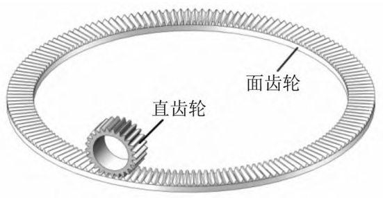
The face gear pair consists of a spur gear and a face gear, as shown in Figure 1.It is a new type of gear transmission mechanism, which has the advantages of stable transmission, vibrationSmall size, low noise and other advantages have been successfully applied to the main reducer of helicopters.The gear transmission system is difficult to wear out under long-term operation.to avoid and gradually worsen, resulting in reduced transmission accuracy, increased vibration noise,Therefore, monitoring the wear state of gears in the transmission system to avoid seriousThe occurrence of serious faults is of great significance.Scholars at home and abroad have done research on gear wear and its dynamics.A large number of theories and experiments were conducted to explore the wear characteristics of planetary gears.First, the Archard wear model was applied to straight teeth to analyze the wear pattern of gear profiles.Using the Archard model, the wear characteristics of planetary gears were investigated.The wear prediction model studies the impact of gear wear on the meshing stiffness.Based on the above research, the wear-induced planetary gears were analyzed.Dynamic response of the wheel.Also established using Archard’s formulaThe wear model of planetary gears is established, and dynamic loads are considered in the model.The influence of the wear of convex double helical gears is consideredThe coupling effect of lubricated elastohydrodynamic lubrication and Archard model is considered.The non-uniform grinding of spur gears is obtained by combining the potential energy method and the Archard formula.The results confirm that non-uniform wear can lead to a decrease in stiffness amplitude.The Archard model was applied to establish the quasi-static and dynamicA wear model for helical gears under conditions of elastohydrodynamic lubricationand Archard model, established a wear prediction model for helical gears, and studiedThe dynamic response of the wear of helical gears was obtained and verified through experiments.Archard’s formula was introduced in the analysis of contact between quasi-hyperbolic gears, resulting in accurate wear measurements.The Archard wear equation is introduced into the wear problem of hypoid gears.The transmission error of the gear was calculated and verified by experiment.This research has promoted the development of gear wear failure and dynamics, providingTheoretical basis, but face gear transmission has some differences with straight gear transmission, helical gear transmission, etc.The wear mode and response characteristics are not clear, so further research is needed.Study on the dynamic response and failure mechanism of face gear transmission systems with non-uniform wear faultsObstacle characteristics, which can contribute to the development and diagnosis of face gears.
This article proposes a surface wear model based on the Archard wear model.The tooth surface contact analysis method of gear pair quantitatively calculates theWear amount of meshing cycle change.Wrote a five-dimensional surface gear pair with wearcoordinate of tooth model surface, and calculated the transmission systemTime-varying meshing stiffness.Based on the lumped parameter method, a dynamic model of a face gear pair is established.The mechanical model equates wear to static transmission error, and uses the Runge-The Kutta numerical integration method was used to solve the motion equation and study different wear conditions.The following are typical dynamic characteristics of the gear pair system.
TCA model of tooth surface wear
The calculation of adhesive wear was first proposed by Archard, and the calculation formula is
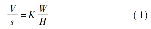
Where: V is the volume of the worn material;s is the relative sliding distance of the contact surfaceL: distance;K: dimensionless wear coefficient;W: normal contact force;H: materialHardness.During the meshing process of gears, the wear depth h of the gear meshing pointcan be expressed as
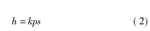
Wherein, k is the wear coefficient, usually obtained from empirical formulas, and is taken as 1 × 10 - 18 N/m2;p is the contact stress.Figure 2 shows the TCA model of a face gear pair, where four coordinate systems Sf,S1, Sd, S2 are represented as fixed coordinate system, spur gear coordinate system, and face toothThe auxiliary coordinate system of the wheel and the coordinate system of the face gear.Straight gear and face gearDon’t engage by rotating in their respective coordinate systems.φ1 and φ2 are the respectiveThe rotation angles of the self-tooth surface in its coordinate system, Rf1, Rf2, and nf1, nf2, are respectivelyThe position vector and normal vector of the tooth surface in the fixed coordinate system, B is theThe difference in the radii of the wheel index circles.When the spur gear and the face gear are in contact, Rf1,Rf2 and nf1, nf2 are equal, that is, the contact equation is
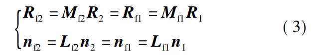
Where, Mf1 and Mf2 are the coordinate transformation moments from S1 and S2 to Sf阵;Lf1 and Lf2 are Mf1 and Mf2 without the last row and columnThe matrix;R1, R2 and n1, n2 are the two tooth surfaces in their respective coordinate systemsThe bit vector and normal vector.In TCA, the meshing circumference of a tooth surface is usuallyThe period is divided into M equal parts, and the meshing position is discretized into a finite number of contact points.By discretizing φ2 and substituting it into equation (3), the solution of the face gear pair can be obtained.Theoretical contact path and position vector and normal vector of contact point after discretization.At the same time,Due to the elastic deformation of the tooth surface, the instantaneous contact of the tooth surface at a certain point will expandis an elliptical region, with instantaneous contact with the symmetrical center of the ellipse and theoretical contactWhen the points coincide, the resulting contact trace is a set of contact ellipses.BecauseThe major axis 2a of the contact ellipse is much longer than the length of the minor axis 2b, if notTaking the short axis of the ellipse into account, under the action of load, the contact ellipse will expand along its long axis.Therefore, the long axis of the ellipse can be discretized into a finiteThe wear parameters of the discrete points of the ellipse are obtained by their discrete position vectors,Calculate the wear depth of the face gear pair again.
Where: v is the relative speed;Δt is the time interval between the nth contact point and the n+1th contact point on the two tooth surfaces.The time used by n + 1 contact points is expressed as
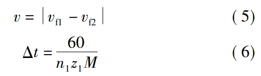
In the formula, vf1 and vf2 are the fixed and rotating speeds of the spur gear and face gear in the face gear pair, respectively.Relative speed in the coordinate system;n1 is the speed of the spur gear, in r/min;z1 is the number of teeth of the spur gear.The contact of any discrete points on the long axis of the ellipse on the tooth surfaceThe stress p can be expressed as
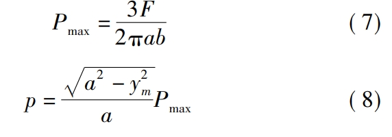
Where, Pmax is the maximum stress of discrete points on the long axis of the ellipse, i.e. contactStress of point;F is the normal contact force acting on the contact point;ym is the contactThe distance of any discrete point m on the ellipse from its contact ellipse center.Due to the wear cycle, the tooth surfaces of the face gear pair will change.Contact stress and relative sliding distance, so the face gear pair is in N cyclesThe wear depth hNN at any point on the rear tooth surface can be written as
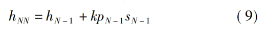
Wherein: hN - 1 is the wear depth after N - 1 cycles;pN - 1 is N - 1Contact stress after N-1 cycles;sN-1 is the relative contact stress after N-1 cyclesDisplacement.In gear transmission, tooth surface wear is a cyclic and cumulative process.Due to the small changes in p and s between each cycle, the computational complexityAnd it will not have a significant impact on wear, so this article ignores the effects of p and s onConsider the change of tooth surface after N cyclesThe wear depth hN is
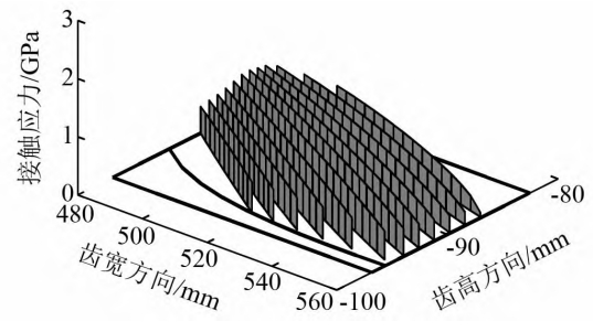
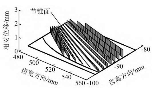
Figure shows the distribution of contact stress on the tooth surface of the face gear pairFigure, due to the transmission characteristics of the face gear pair, near the pitch circle and pitch cone isSingle tooth contact, the contact stress is high.While near the root and tip of the toothAt the top, the face gear pair changes from single tooth pair contact to double tooth pair contact,The contact stress is relatively small, so the stress distribution on the tooth surface is from the root to the tipThe top shows a trend of increasing first and then decreasing.Figure 1 shows the surface gear pair in theThe relative displacement distribution on the gear tooth surface is determined by the relative position of the two tooth surfaces on the pitch circle and pitch line.The motion at the conical surface is relatively static, and the relative position of the moving object when it is far away from this areaIncreasingly, the contact area between the gear teeth near the tooth root and tooth tipThe relative displacement is the largest, and the closer to the center, the smaller the relative displacement, and it is at the pitch circleand maintain a stationary state with a relative displacement of 0 at the joint conical surface.
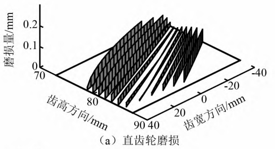
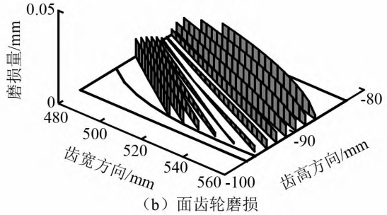
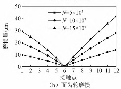
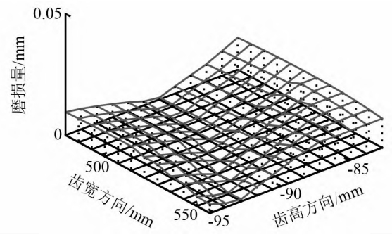
The figure shows the wear distribution of the tooth surfaces of the spur gear and face gear in the face gear pair obtained based on the contact stress and relative displacement.It can be seen that the wear on the tooth surfaces of the spur gear is more severe than that of the face gear.The wear of gears and face gears from the root to the tip decreases first and then increasesThe wear amount near the pitch circle and pitch cone is veryThe small change trend is the same as that of relative displacement, indicating that relative displacement has a significant effect on the tooth surfaceThe influence of wear is greater than that of contact stress.The difference is that the tooth root wear of spur gearsThe wear is more serious, and the wear on the tooth top of the face gear is greater.And it is different from the straightThe phenomenon of gear pair with zero theoretical wear amount on the pitch circle, face gear pairOnly the wear around the contact point is 0 at the pitch circle and pitch cone, and the restThere is still a slight wear on the place.The picture shows the spur gear andThe wear amount of the tooth surface contact point of the face gear under different cycle times.In the middle, the first contact point of the face gear is located at the root of the tooth, and the 12th contact pointThe point is near the tooth tip, while the spur gear is the opposite.As can be seen from the figure, theThe increase in the number of cycles will directly lead to increased wear.

time-varying meshing stiffness model
Calculate the tooth surface wear depth of the face gear pair under different cyclesAfter that, the tooth surfaces are reconstructed, and the position vectors of the two tooth surfaces after reconstruction areR1h and R2h can be expressed in their respective coordinate systems as
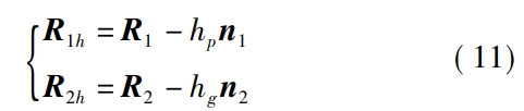
In the formula, hp and hg are the respective tooth heights of the two tooth surfaces after N wear cycles.The wear depth of any point on the surface.By measuring the wear depth of the driving side tooth surface and the driven side tooth surface of the two tooth surfaces,The non-driving side tooth surfaces are obtained symmetrically, and theThe straight gear and face gear single tooth are filled with sections between the worn tooth surfaces on both sidespoints to form the finite element nodes of the single tooth of the two gears;separately calculate theThe finite element nodes rotate by integer teeth around their respective axes to form multiple teethFinite element nodes;according to the writing rules of the finite element grid, the two teeth areThe nodes of the multi-tooth finite element are numbered sequentially, forming a multi-tooth finite element meshThe lattice model enables the tooth surface coordinates to be included in the calculation even when there are micrometer-scale changes.In the finite element model, the difficulty of changing the micro-surface morphology due to theThe detailed error caused by insufficient accuracy in generating the mesh with software is too large;and the pre-processing bar for the basic parameter settings of the face gear pair in Table 1Input the grid model, pre-processing settings, and other information into the batch processing inpThe remaining steps are completed in the file and through the command flow of finite element software.Then use the ABAQUS solver to solve the face gear pair with normal and worn conditionsNonlinear contact problems.
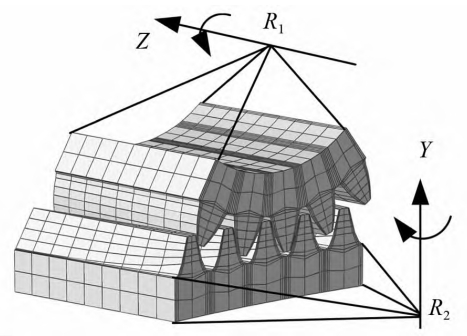
The figure shows a 5-tooth model of a face gear pair, with the indicated grid density (tooth width × tooth depth).The tooth height × tooth thickness is 5 × 10 × 4.To ensure accuracy, the mesh of the numerical example modelThe grid density is 51 × 81 × 4.The figure shows the equivalent of wear as a tooth surface deviation.The schematic diagram of the differential surface of the face gear after the differential, as can be seen from the figure,The face gear has a large tooth surface deviation at the tooth root and tooth tip, but on the pitch cone surfaceThe deviation of the adjacent tooth surfaces is very small.
Using the third pair of teeth in the five-tooth model as the observed pair, theThere are 20 meshing points in the whole process of meshing in and out, and each meshing point is obtainedThe angular deformation θg at the gear mesh point is converted into theComprehensive elastic deformation δnThe expression is
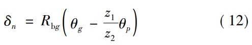
Wherein: Rbg is the base circle radius of the face gear;θp is the angular deformation of the spur gear;z2is the number of teeth of the face gear.Then, the time-varying meshing stiffness km of the face gear can be obtained asExpression:
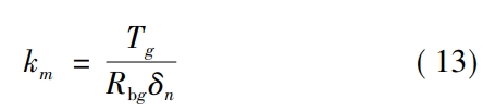
Where, Tg is the torque of the face gear.The meshing stiffness is fitted into Fourier seriesForm of
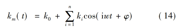
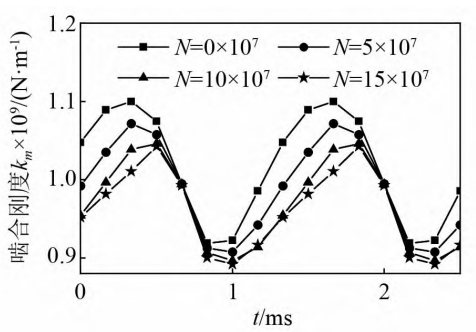
Where, k0 is the average value of meshing stiffness;ω is the meshing frequency, ω =2πn1 z1 /60, where n1 is the speed of the spur gear, z1 is its number of teeth, and φ is the initialThe phase is generally set to 0.Figure 9 shows the normal and 3The meshing stiffness under different wear cycles can be seen, and it can be observed that the tooth surface wearThe loss will reduce the amplitude of the gear meshing stiffness, and the more severe the wear, the lower the meshingThe smaller the amplitude of stiffness.
Static transmission error of gear without load
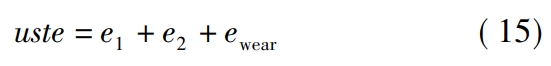
Gear error is a displacement excitation during the meshing process, while static transmissionThe error is mainly caused by tooth deformation and gear error.Unloaded static transmission error (USTE)It is caused by tooth profile deviation, mainly including manufacturing errors, tooth profile modification, and toothThe static transmission error is divided into rotational frequency error e1, comprehensive error e2, and transmission error ewear caused by gear wear, that is,
frequency conversion error
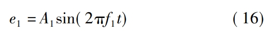
Where, A1 is the amplitude of shaft frequency error, and in this article, A1 is taken as 55 μm;f1 is the mainRotation frequency of the moving wheel.Overall error
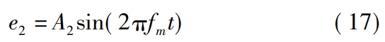
Where, A2 is the amplitude of the comprehensive error, which is taken as 25 μm in this article;fm is the toothWheel engagement frequency.Equivalent to tooth profile deviation due to gear wearEp and Eg
Where, p and g are the driving wheel and the driven wheel respectively.From this, we obtain the gear grinding equationTransmission error caused by loss
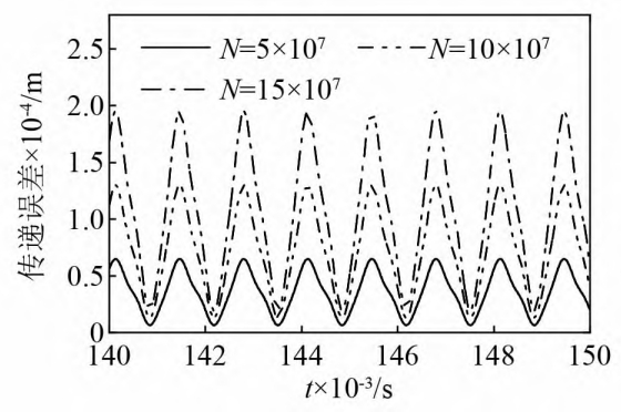
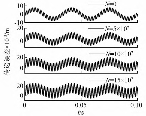
Where: Eil is the deviation value of tooth pair l, and i = p, g;nl is the simultaneous participationThe number of teeth engaged.The figure shows the wear caused by gear wear under different wear cyclesThe transmission error ewear can be seen from the graph that ewear varies with the gear meshing cycleIt changes regularly, and as the wear increases, its amplitude will also increase.but unlike the transmission error of two gears in a spur gear pair, which isThe lowest point of transmission error of face gear pair is when the amplitude is 0 at the bottomIt will rise slightly with the increase of wear, because the straight tooth profile in the face gear pairGears and face gears only have a small portion of wear near the pitch circle and pitch coneThe damage is 0, and the rest has minor wear.The figure shows different wear cycles.The static transmission error under the number of cycles mainly consists of rotation frequency and meshBy combining the frequencies, it can be seen that wear will increase the magnitude of the static transmission error.
kinetic model
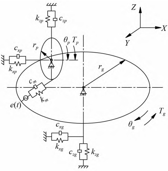
Establishing the multi-degree-of-freedom dynamics of face gear pairs based on the lumped parameter methodThe model considers 6 degrees of freedom of vibration in the transmission system, as shown in Figureincluding the bending vibration of spur gears and face gears in the X direction.The bending vibration degree of freedom zp;of the spur gears in the Z direction isAxial vibration degree of freedom of gear in Z direction zg;spur gear around Y axis directionThe torsional vibration degree of freedom θp;the torsional freedom of the face gear around the Z axis directionThe relative displacement xn is expressed as
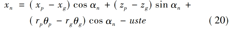
In the formula, rp and rg are the meshing radius of the spur gear and face gear respectively;αnis the pressure angle of the face gear pair, and uste is the static transmission error of the face gear pair.
Typical dynamic characteristics of worn gear pairs
The Runge-Kutta numerical method is used to solve equation (23) to obtain the surface toothThe dynamic response of the wheel transmission.Among them, the speed of the spur gear n1 =1 800 r/min, face gear speed n2 = 281.25 r/min, gear pair meshThe harmonic frequency fm = 750 Hz, the direct gear rotation frequency f1 = 30 Hz, and the face gear rotation frequencyf2 = 4.69 Hz.
The influence of wear on dynamics
Fig. and Fig. respectively show the normal meshing and wear of the face gear pairDynamic meshing force and spur gear xp under the condition of cycle number N = 15 × 107The acceleration time-domain signal, frequency-domain signal, and envelope spectrum signal of the vehicle are shown in FigureIt can be seen from Figure 1 that as the wear increases, the dynamic meshing force and xp accelerationThe amplitude of the response increases continuously, without any sudden changes in amplitude.The spectrum and envelope spectrum are dominated by the meshing frequency and its harmonics, and grow rapidly.The sideband of the carrier wave with the meshing frequency and its multiple frequency also showed a slow increase in amplitude.The number of long and sideband frequencies increases.In addition, the envelope spectrum showsWeak frequency conversion information, and its amplitude will also slightly decrease with the increase of wearThis is because the wear of the tooth surface not only changes the static transmission error,It will also be reflected in the frequency conversion.Cepstrum, as one of the commonly used signal processing methods, can extractThe original spectrum is difficult to identify complex periodic signals, so it is widely used inIn more complex vibration conditions, such as gear tooth failure and shaft misalignment.Compared to spectral analysis, which identifies the main frequency components of a signal, cepstrum is better atIn order to extract the fault frequency, the cepstrum analysis is used in the vibration analysis of gears.Therefore, this article analyzes the surface roughness of normal meshing and wear.By conducting cepstrum analysis on the vibration signal of the gear pair, as shown in the figure, it was found thatAs the wear increases, the frequency shift information in the cepstrum becomes more and more obvious.
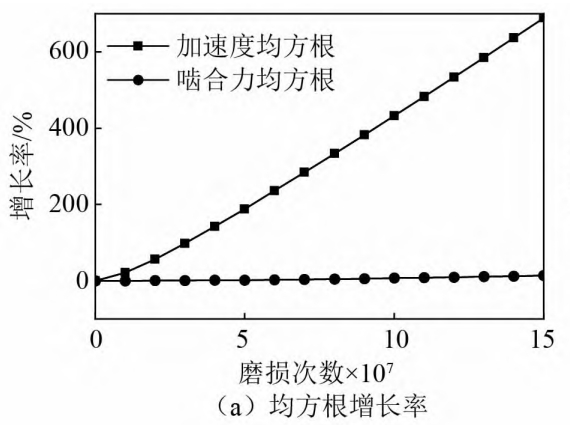
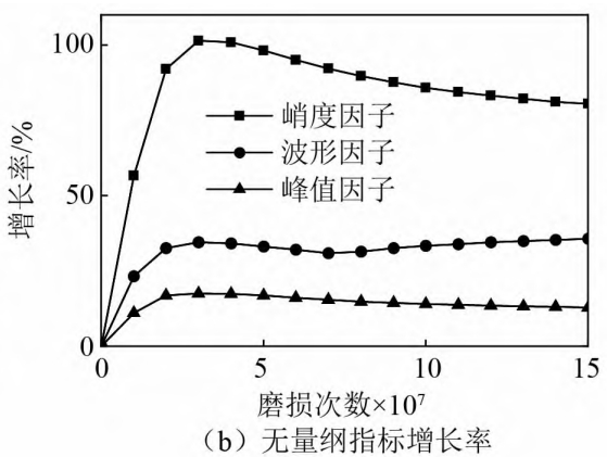
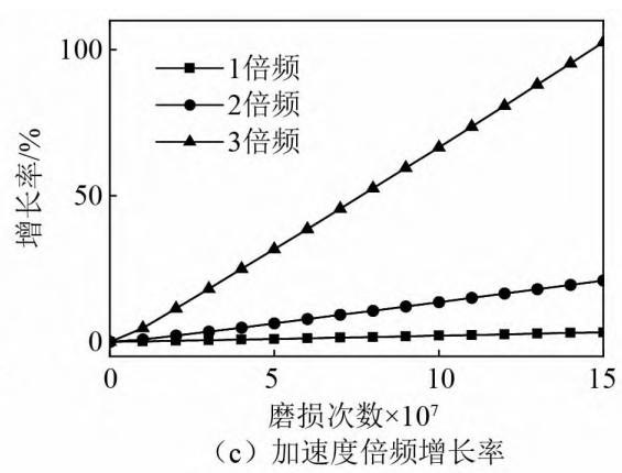
Growth rate of wear index
Analyzed the effect of root mean square on meshing force and xpThe change trend of speed in the wear process is shown in Figure (a).The growth rate of the root mean square of acceleration is much greater than that of the meshing force, indicating that the root mean square of acceleration is more sensitive to wear than the root mean square of meshing force.Later, in Figure (b), we explored the kurtosis factor, waveform factor, and peak factor.Three non-dimensional statistical indicators in the time domain for acceleration during wearChange situation, we can see that among the three non-dimensional statistical indicators, the growthThe trend of the rate is to increase first and then remain basically unchanged, indicating that there is no volume in the early stage.The indicators are more sensitive to early wear, but cannot be used to judge severe wearThe basis.
The influence of torque on wear and dynamics
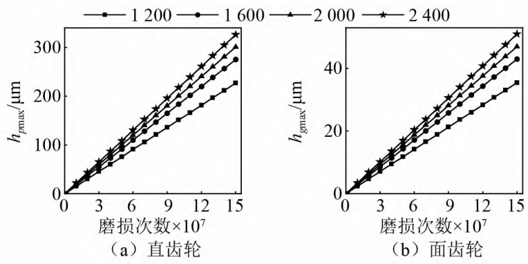
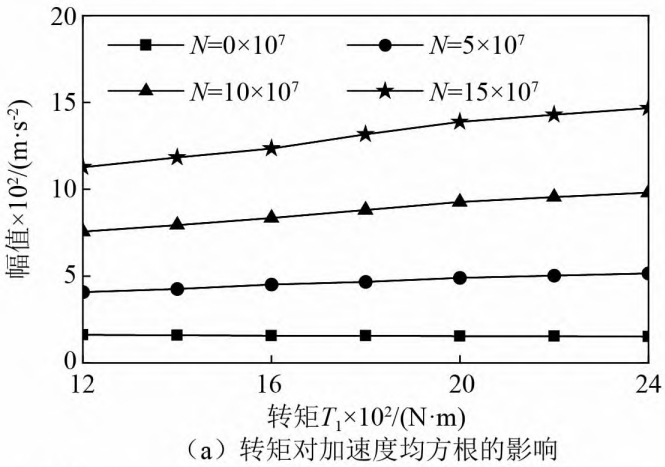
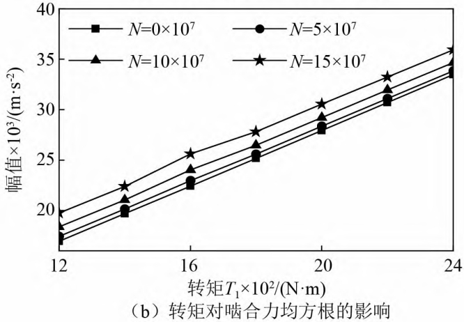
The maximum wear amount of spur gear in face gear pair, hpmax, and the maximum wear amount of face gear, hpmax,The maximum wear amount hgmax is shown in Figure (a) and Figure (b), respectively, whereThe unit of torque is N·m.It can be seen from the figure that as the torque T1The increase in hpmax and hgmax is constantly increasing because of the increase in torque.The contact pressure on the gear tooth surface increases, and it can be seen from formula (2) that the contact stress andThe wear depth of the gear is proportional, which can be inferred that the torque is alsoOne of the causes of wear in gear pairs.Figure (a) shows the torqueThe effect of root mean square velocity, when there is no wear, the acceleration root mean square does not vary with rotationThe increase in torque will cause significant changes. Once wear begins, the torqueThe increase in the acceleration of the more severe wear condition is more obvious.However, the root mean square of the meshing force always increases with the increase of torque, and does not change withThe wear changes significantly, as shown in Figure (b).
Conclusion
(1) In the wear of face gear pairs, the wear near the tooth root and tooth tip is the largest, and the wear on the pitch circle and pitch cone surfaces is 0 except for the contact point.There is also slight wear in the remaining area;the magnitude of the meshing stiffness will increase with the wear of the tooth surface.The loss is serious and continuously decreasing;the wear of the tooth surface will produce a wear pattern with a meshing cycle ofThe transmission error of the main shaft increases with the increase of wear, and the amplitude of the static transmission errorthe value also increases significantly.(2) Time-domain and frequency-domain amplitude of dynamic meshing force and acceleration responsewill increase with the increase of wear, and appear faintly in the envelope spectrumfrequency conversion and weak modulation with the meshing frequency and its multiple as the carrierThe information of the axis frequency in the cepstrum will become more and more obvious.Compared to the case withoutThe indicator of 纲 indicates that the acceleration root mean square is more sensitive to the serious wear of the face gear pair.The acceleration 3rd order frequency amplitude increases rapidly with the increase of wear.(3) Increased torque will lead to increased wear and accelerateThe root mean square amplitude increases, but the change in torque does not affect the average meshing forceVariation of the square root amplitude.