1. Dynamic simulation modeling of pitting helical gear pairs

The pitting corrosion of helical gears generally occurs near the pitch line or tooth root of helical gears. Based on the parameters of helical gears in Table 1 and the actual pitting size of helical gears, different types of pitting corrosion helical gear models are established. The fault simulation setting shows slight pitting on the single tooth surface [Figure 1 (b)], with dimensions of 5 mm on the long axis and 1 mm on the short axis A 5mm elliptical plane; Severe pitting on a single tooth surface [Figure 1 (c)], with dimensions of 10 mm on the major axis and 1 mm on the minor axis A 5mm elliptical plane; Double tooth surface pitting [Figure 1 (d)] occurs on two tooth surfaces, one of which is a major axis of 5 mm and a minor axis of 1 A 6mm elliptical plane, with the other one having a major axis of 10mm and a minor axis of 1mm A 5mm elliptical plane; Multiple tooth surface pitting [Figure 1 (e)] On three tooth surfaces, the first is an elliptical plane with a major axis of 8 mm and a minor axis of 3 mm, and the second is an elliptical plane with a major axis of 14 mm and a minor axis of 1 A 6mm elliptical plane, the third being a rectangular plane with a length of 4mm and a width of 1mm. The pitting depth is all 0 2 mm.
Import the established geometric model of the pitting helical gear into the dynamic simulation software for dynamic simulation. The specific process is as follows:
1) Add rotating pairs to the four shaft ends based on the actual meshing transmission relationship.
2) Apply a driving speed of 2500 r/min to the driving gear and a load of 840 N · m to the driven gear.
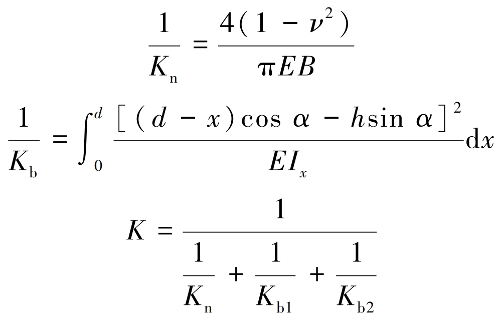
3) Calculate the meshing stiffness K of the solid contact between two helical gears. The comprehensive elastic deformation of gear teeth includes bending deformation, contact deformation, shear deformation, and deformation of supporting structures, shafts, and bearings. For the research content, this article mainly considers bending deformation and contact deformation, and the calculation formulas are:
| Gear | Number of teeth | Normal modulus/mm | Pressure angle/(°) | Helix angle/ (°) | Tooth width/mm |
| Driving gear | 17 | 2.1 | 17.5 | 29 | 19.8 |
| Driven gear | 60 | 2.1 | 17.5 | 29 | 16.9 |
In the formula, Kn is the contact stiffness; Kb is the bending stiffness (subscripts 1 and 2 represent the driving and driven wheels respectively); E is the elastic modulus; ν Poisson’s ratio; B is the meshing tooth width; I x is the moment of inertia of the cross-section at the distance between the gear teeth and the base circle x; D is the distance between the meshing point and the base circle in the direction of tooth height; H is the distance from the meshing point to the centerline of the helical gear; α The angle between the meshing force and the perpendicular direction of the centerline of the helical gear.
| Meshing stiffness/ (N/mm) | Collision index | Damping coefficient | Penetration depth/mm |
| 3. 741×10^5 | 1.5 | 48 | 0.1 |
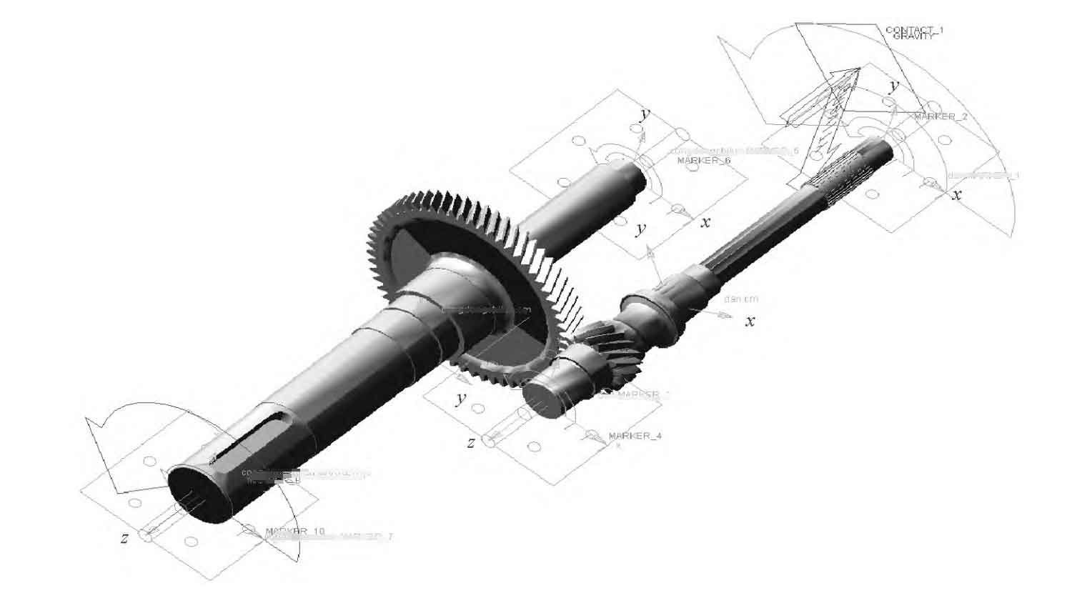
4) Add contact based on the meshing parameters of the helical gear pair shown in Table 2, set the material properties of the helical gear according to Table 3, and establish a dynamic simulation model as shown in Figure 2.
| Material | Density/( kg/m^3 ) | Modulus of elasticity/GPa | Poisson′s ratio |
| 20MnCrS5 | 7840 | 210 | 0.278 |
2. Simulation signal analysis of different pitting degrees on a single tooth surface
The Hilbert envelope spectrum transformation of the original signal in the frequency domain can be defined as:

In the formula, t represents time; τ For a certain moment.
The rotational frequency of the helical gear is:
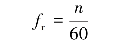
In the formula, n is the rotational speed of the helical gear.
The meshing frequency of the helical gear is:
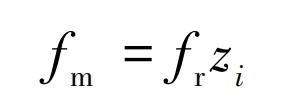
In the formula, zi is the number of teeth of the helical gear.
After calculation, the rotational frequency of the small helical gear is fr=42 Hz, and the meshing frequency of the two helical gears is fm=708 Hz.

In the time domain, analyzing Figure 3 and comparing it with a normal helical gear [Figure 3 (a)] and a slightly pitting helical gear with a single tooth surface [Figure 3 (b)], it was found that the latter only increased by 2% in amplitude. However, for gears with severe pitting on a single tooth surface [Figure 3 (c)], compared to normal helical gears, the overall amplitude increases by 3% and is accompanied by significant impacts, with an impact period of 0 024 seconds, with the same rotation cycle as the faulty helical gear.

In the frequency domain, analyzing Figure 4, normal helical gears [Figure 4 (a)] only have two peak frequencies of meshing frequency fm and twice the meshing frequency 2fm, while helical gears with slight single tooth surface pitting [Figure 4 (b)] have three peak frequencies of rotational frequency fr, twice the rotational frequency 2fr, and three times the rotational frequency 3fr in the low-frequency region. In the high-frequency region, there are sidebands with a difference of fr between the meshing frequency fm and twice the meshing frequency 2fm. The phenomenon of severe pitting on a single tooth surface in helical gears [Figure 4 (c)] is consistent with slight pitting on a single tooth surface, but the overall amplitude increases by 9%, and the number of sidebands in the high-frequency region increases near the meshing frequency fm and twice the meshing frequency 2fm.
3. Analysis of simulation signals for pitting corrosion on multiple tooth surfaces
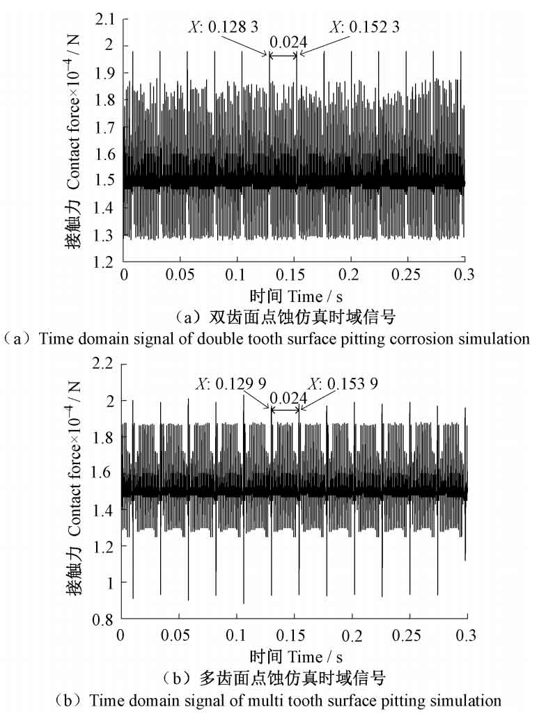
In the time domain, analyzing Figure 5, the helical gear with double tooth surface pitting [Figure 5 (a)] showed a 9% increase in overall amplitude compared to the gear with severe pitting on a single tooth surface [Figure 3 (c)], and also exhibited significant periodic impacts with a period of 0 024 s is the rotation cycle of the faulty helical gear, which has a greater impact amplitude than the occurrence of severe pitting on a single tooth surface. The overall distribution of contact force in helical gears with multiple tooth surface pitting corrosion [Figure 5 (b)] becomes sparse, and the overall amplitude shows no significant change compared to double tooth surface pitting corrosion, but more impacts with larger amplitudes occur, and the period remains 0 024 seconds.
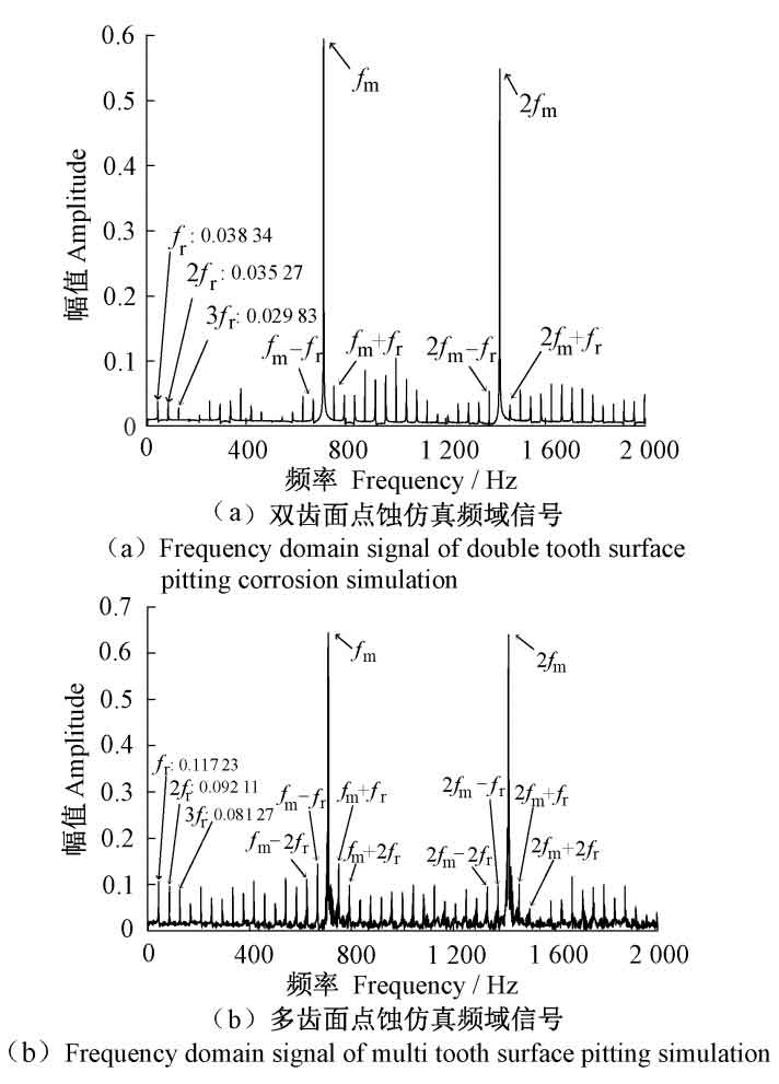
In the frequency domain, analyzing Figure 6, the helical gear with double tooth surface pitting [Figure 6 (a)] showed severe pitting compared to the single tooth surface [Figure 4 (c)]. In the low frequency range, three peak frequencies, namely rotation frequency fr, twice rotation frequency 2fr, and three times rotation frequency 3fr, were also observed, with an increase in amplitude of 46%. In the high-frequency region, the amplitude of the meshing frequency fm and twice the meshing frequency 2fm increases by 5%, and there are more nearby sidebands with larger amplitudes. The helical gear with multiple tooth surface pitting corrosion [Figure 6 (b)] showed a 150% increase in amplitude at the low frequency range of rotation frequency fr, twice the rotation frequency 2fr, and three times the rotation frequency 3fr, while the amplitude at the high frequency range of meshing frequency fm and twice the meshing frequency 2fm increased by 8% compared to the double tooth surface pitting corrosion. A large number of high amplitude sidebands appeared nearby. And it was found that when more than one helical gear tooth surface undergoes pitting, the number and amplitude of the sidebands between 0 and 800 Hz increase with the increase of the number of pitting tooth surfaces.

