
The simulation process of helical gear dynamic contact has been introduced in detail before. The mesh division is also divided in HyperMesh and imported into ANSYS / LS-DYNA. The solid element is solid164, and the outer ring surface of the helical gear shaft is defined as shell163 element. At the same time, the translational displacement and the degree of freedom of rotation around the X and Y axes are constrained, and the helical gear can only rotate freely around the Z axis. Here, the shell163 element is defined for the outer ring of the helical gear shaft. It should be noted that because the length of the helical gear shaft is relatively long, considering the influence of the shaft stiffness on the contact stress of the helical gear, according to the actual working conditions, some helical gear shafts on the right side of the helical gear shaft do not define the shell163 rigid body element, as shown in Figure 1-3. After defining the element type, real constant and material properties, it is necessary to define part and contact, and finally apply load. The specific position of load application in the actual working condition is shown in Figure 1-3. There are two pairs of helical gears meshing in the model of fourth gear helical gear pair of a transmission, and two contacts need to be defined. Since there are two pairs of helical gears meshing here, but the power is transmitted through the helical gear meshing under the action of the helical gear shaft, according to the actual working conditions, a constant input torque is applied to the input helical gear and a constant load torque is applied to the output helical gear.
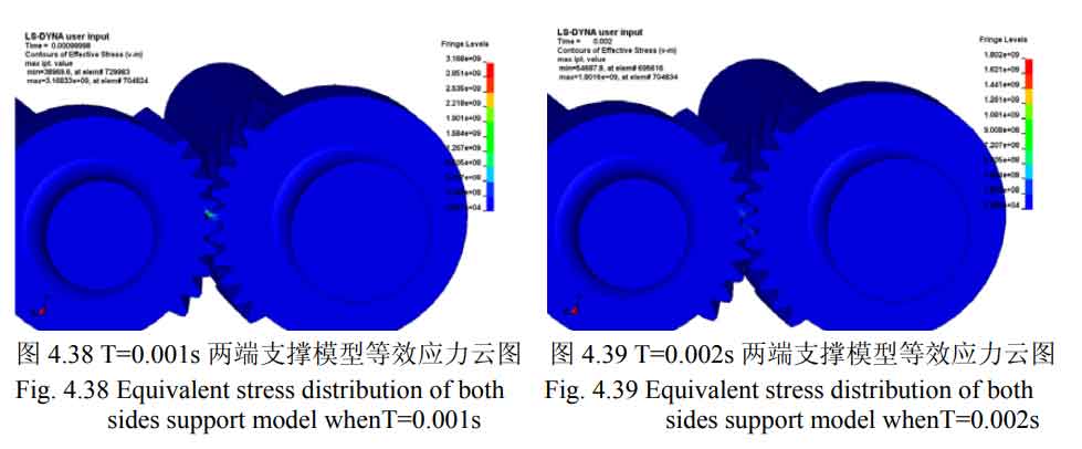
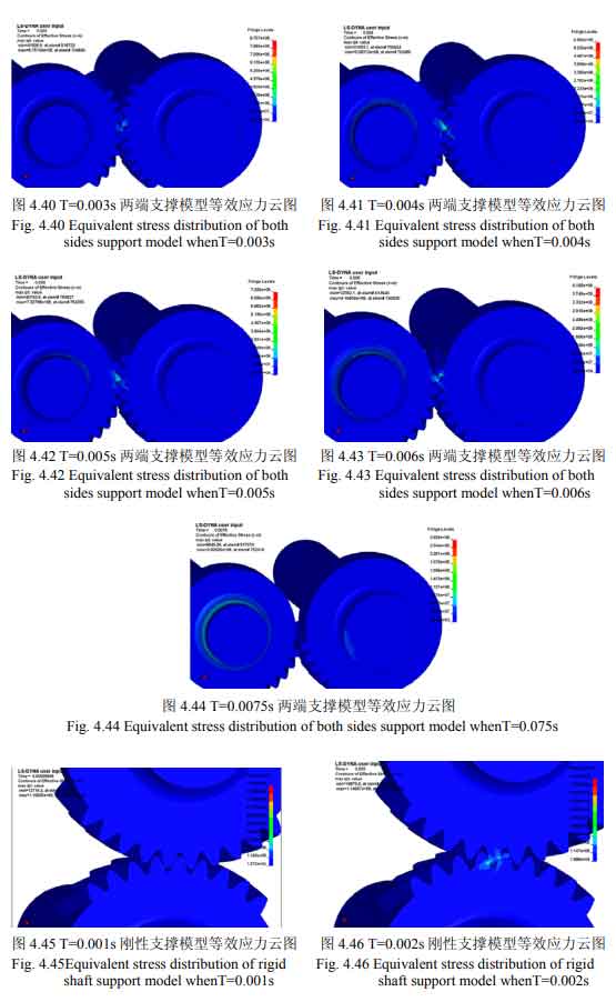
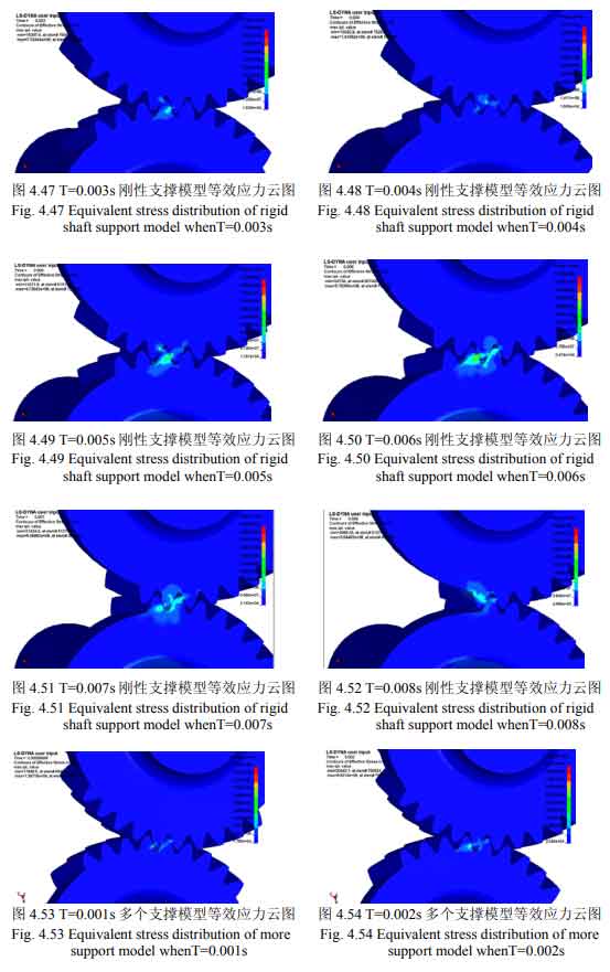
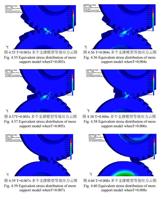
There are two pairs of helical gear pairs in the fourth gear helical gear pair model of a transmission. In order to facilitate the comparison with the helical gear model, only the change of contact stress of the second shaft fourth gear helical gear and the intermediate shaft fourth gear helical gear in the meshing process is studied. Figure 4-26 shows the maximum equivalent stress nephogram of two end supported helical gear model, rigid shaft supported helical gear model and multiple supported helical gear models. Since there are many frames of dynamic contact simulation animation, in order to facilitate the comparison of stress results, the maximum equivalent stress in each frame of animation is the ordinate and the meshing time is the abscissa, which are programmed in MATLAB. Fig. 27 and Fig. 28 are the maximum equivalent stress change curves of the main and driven wheels of two end supported helical gear model, rigid shaft supported helical gear model and multiple supported helical gear models in each frame, It can be seen from the figure that no matter what model, the equivalent stress of the driving and driven wheels is large at the beginning of meshing and rotation. This is because the loading of the whole helical gear model is directly added to the torque in the stable state from zero. During this period, the impact vibration is relatively large. After the helical gear is meshed for a certain time, the contact stress of the helical gear tends to be stable.
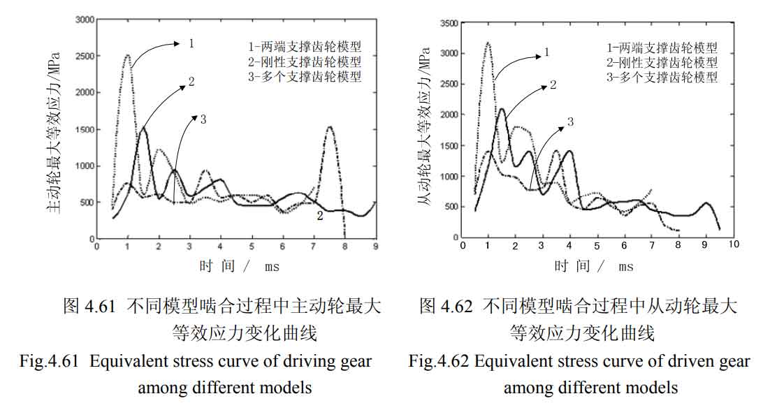
The equivalent stress of the helical gear model supported at both ends in the whole meshing process is slightly greater than that of the rigid shaft supported helical gear model and multiple supported helical gear models. This is because the whole helical gear long shaft of the helical gear model supported at both ends is placed in space without any support position, and the helical gear shaft is prone to large bending deformation, which is easy to cause instability of the gear pair in the meshing process, Therefore, its equivalent stress is slightly larger than that of the other two models; It can also be seen from the figure that the stress of the helical gear model supported by the rigid shaft is slightly greater than that of multiple helical gear models. This is because the loading mode of the helical gear model supported by the rigid shaft is to define the outer ring of the whole helical gear shaft as a rigid body. The rigidity of the whole model is relatively large, but the helical gear shaft is not flexible, forming an over positioning.
To sum up, the helical gear shaft is easy to produce bending deformation in the meshing process of helical gear, and its deformation is easy to cause unstable meshing of helical gear and produce large impact stress.