
For high-precision hypoid gear pairs, in order to increase the actual coincidence degree after loading, the design of large inclination of contact path is mainly considered. Taking the working surface of a pair of spiral tooth hypoid gears as an example, the basic parameters are shown in Table 1. The rated torque of the large wheel is 1000N · m, the input speed of the small wheel is 5000 r/min, and the maximum shaft frequency error is a = 3 μ m; The optimized optimal ease off surface parameters are shown in Table 2. In order to study the relationship between the amplitude of load-bearing deformation (the amplitude of stiffness) and vibration after modification, table 3 lists the Alte, the ratio of normal vibration acceleration and the corresponding value of conjugate tooth surface of different modified hypoid gears in the optimization iteration process (optimization force). The Alte of the optimized ease off tooth surface is reduced to 65% and the normal vibration is reduced to 15%, while the Alte of the optimized ease off hypoid gear tooth surface 1 is basically unchanged, but the normal vibration is reduced to 22%; It can be seen that when Alte is the smallest, the vibration may not be the smallest. The normal vibration is not only related to the amplitude of bearing deformation, but also related to the shape of bearing deformation curve.
| Parameters | Hypoid gear pinion | Hypoid gear wheel |
| Number of teeth | 8 | 41 |
| Midpoint helix angle / (°) | 48.93 | 30.63 |
| Rotation direction | Sinistral | Dextral rotation |
| Addendum height /mm | 5.77 | 1.50 |
| Tooth root height /mm | 1.16 | 5.73 |
| Pitch cone angle / (°) | 12.53 | 76.82 |
| Face cone angle / (°) | 17.45 | 77.73 |
| Root cone angle / (°) | 11.67 | 71.68 |
| Outer cone distance /mm | 97.19 | 84.72 |
| Tooth width /mm | 28 | 24 |
| Distance from pitch cone vertex to intersection /mm | 13.84 | -1.43 |
| Offset distance /mm | 23 | — |
| Radial support stiffness / (n · m - 1) | 500000000 | 500000000 |
| Axial support stiffness / (n · m - 1) | 250000000 | 250000000 |
| Bearing support damping coefficient | 0.005 | 0.005 |
| Meshing damping coefficient | 0.1 | 0.1 |
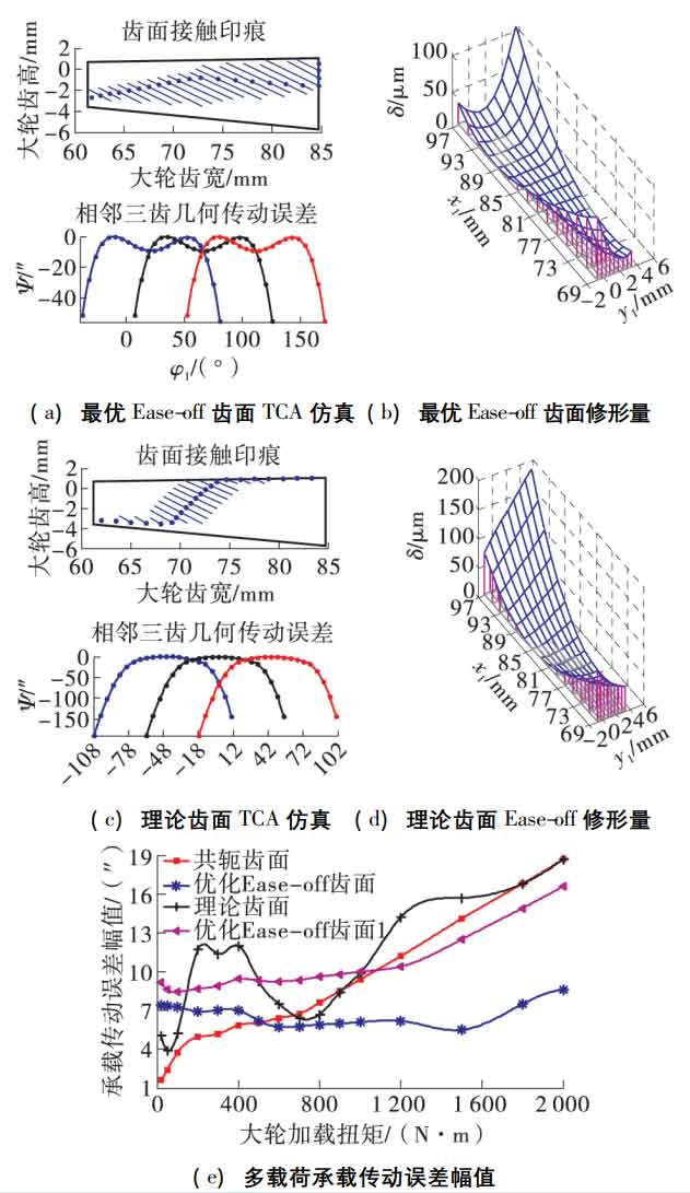
The TCA simulation of the tooth surface of the optimal ease off hypoid gear is shown in Figure 1 (a). There is a certain amount of modification at the meshing in and meshing out ends, which is close to the inner diagonal contact; The TCA simulation of the theoretical tooth surface is shown in Figure 1 (c). It is an internal diagonal contact, and has a certain amplitude at the meshing conversion point, which can reduce the sensitivity of the installation error, and the fitting amount of the hypoid tooth surface is large; The ease off surfaces of the two are shown in Fig. 1 (b) and (d), which are consistent with the contact area respectively. The larger the transmission error is, the larger the tooth surface modification of the corresponding hypoid gear is.
| Backlash parameters | numerical value |
| ε0 / ( ” ) | -7.9 |
| ε1 / ( ” ) | -2.3 |
| ε2 / ( ” ) | -2.3 |
| ε3 / ( ” ) | -10.3 |
| ε4 / ( ” ) | -12.3 |
| λ 1 / (radian) | 0.44 |
| λ 2 / (radian) | 0.61 |
| d1 /mm | 1.73 |
| d2 /mm | 2.03 |
| q1 /mm | 0.019 |
| q2 /mm | 0.022 |
| θa / ( °) | 10 |
Here, a meshing cycle is divided into 8 equal parts, the TCA contact point is 22, and the theoretical coincidence degree is slightly greater than (22-1) /8 = 2 6。 Multi load Alte is shown in Figure 1 (E). The actual coincidence degree of conjugate tooth surface remains unchanged, and Alte increases with the increase of load; The theoretical tooth surface adaptation is too large and the elliptical long shaft design is too small. With the increase of load, the actual coincidence degree increases differently, so Alte has multiple extreme values; When the optimal ease off hypoid tooth surface adaptation is small and the elliptic long shaft design is large, the coincidence degree increases with the increase of load until it remains unchanged. Therefore, when the load is ≥ 1400 n · m, Alte gradually increases.
| Different modified tooth surfaces | Load transmission error amplitude /% | Meshing line vibration acceleration /% |
| Optimal ease off tooth surface | 65 | 15 |
| Theoretical tooth surface | 105 | 126 |
| Optimize ease off tooth surface 1 | 106 | 22 |
| Optimize ease off tooth surface 2 | 49 | 96 |
| Optimize ease off tooth surface 3 | 56 | 33 |
In the direction of normal degree of freedom, the meshing stiffness of the gear pair is the smallest, the relative vibration displacement is the largest, and the conjugate tooth surface is the opposite; The tooth surface vibration speed of the optimal ease off hypoid gear is the most stable, and it is a single cycle simple harmonic vibration law, as shown in Figure 2 (a). The root mean square of the vibration acceleration of the tooth surface of the optimal ease off hypoid gear is reduced to 15% of the conjugate tooth surface, which is mainly the meshing frequency (666.67 Hz) and 3 times the frequency. The modification mainly reduces the vibration amplitude of 3 times the meshing frequency. It can be seen that the natural frequency of a certain order of the system is close to 2000 Hz, as shown in Figure 2 (b). Similarly, the normal dynamic meshing force of the tooth surface of the optimal ease off hypoid gear changes near the theoretical static meshing force with the minimum amplitude. Fourier transform is performed on the changing part of the meshing force, which is mainly the meshing frequency, 2 times and 3 times, as shown in Figure 2 (c).


