
I propose a compact driving concept for the cover plate of a flat grinding machine in which the cover plate moves with an approximately constant speed during its working stroke. The core idea is to combine high-order modified eccentric pinion gears, conjugate non-circular pinion gears, and a concentric crank-slider mechanism in series. In my design, the input shaft rotates at a constant angular velocity, the eccentric pinion gears produce a controlled non-uniform angular velocity, and the crank-slider mechanism converts that non-uniform rotation into an almost constant-speed reciprocating translation of the cover plate. I develop the kinematic model, analyze the influence of eccentricity and modification coefficients, optimize the parameters with a genetic algorithm, and verify the concept through a virtual prototype. The repeated use of pinion gears in the transmission path is central because the pitch curves of the pinion gears determine the output motion law before the crank-slider mechanism further shapes the cover plate displacement.
Mechanism Architecture and Operating Principle
The mechanism I investigate contains a driving eccentric pinion gear, a driven eccentric pinion gear, a crank, a connecting rod, and a slider that represents the cover plate. The input shaft drives the first eccentric pinion gear at a constant speed. The first eccentric pinion gear meshes with the second eccentric pinion gear, and because the pitch curves of the two pinion gears have a periodically varying radial ratio, the driven pinion gear rotates with a non-uniform angular velocity. The crank is fixed to the driven pinion gear, so the crank inherits the same angular velocity and angular acceleration as the driven pinion gear. The crank then drives the connecting rod, and the connecting rod drives the slider along a horizontal guide. The slider is the cover plate, and its working stroke should be as close to constant speed as possible.
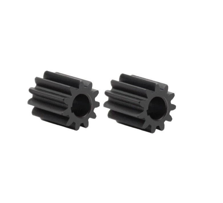
Compared with a conventional cover plate driving system that uses several planar four-bar mechanisms and a cylindrical gear pair, my proposed series combination has a shorter transmission route, fewer components, and a simpler layout. The eccentric pinion gears and the conjugate non-circular pinion gears are the main motion-programming elements. The crank-slider mechanism is the final output stage. I treat the assembly as one integrated mechanism because the output speed of the cover plate depends on both the non-circular pinion gear pair and the crank-slider geometry. The design target is not exact constant speed over the entire cycle, but an approximately constant speed over the useful working stroke while maintaining continuous meshing and convex pitch curves for all pinion gears.
Nomenclature and Design Parameters
| Symbol | Meaning | Symbol | Meaning |
|---|---|---|---|
| \(e\) | eccentric distance of the pinion gear | \(R\) | radius of the equivalent eccentric circle |
| \(m_{11}\) | first modification coefficient | \(m_{12}\) | second modification coefficient |
| \(n_1\) | order of the driving pinion gear | \(n_2\) | order of the driven pinion gear |
| \(r_1\) | pitch curve radius of the driving pinion gear | \(r_2\) | pitch curve radius of the driven pinion gear |
| \(\phi_1\) | rotation angle of the driving pinion gear | \(\phi_2\) | rotation angle of the driven pinion gear |
| \(\dot{\phi}_1\) | angular velocity of the driving pinion gear | \(\dot{\phi}_2\) | angular velocity of the driven pinion gear |
| \(\ddot{\phi}_1\) | angular acceleration of the driving pinion gear | \(\ddot{\phi}_2\) | angular acceleration of the driven pinion gear |
| \(a\) | center distance of the pinion gear pair | \(k\) | eccentricity ratio, \(k=e/R\) |
| \(l_1\) | crank length | \(l_2\) | connecting rod length |
| \(i_{12}\) | transmission ratio of the pinion gear pair | \(s\) | slider displacement |
| \(\dot{s}\) | slider velocity | \(\ddot{s}\) | slider acceleration |
I use these parameters throughout the mathematical derivation. The term pinion gears appears repeatedly because the eccentric pinion gears and the conjugate non-circular pinion gears determine the input to the crank-slider stage. The design variables ultimately selected for optimization are the eccentric distance, the equivalent radius, and the first modification coefficient, while the order ratio and the crank-slider dimensions are fixed by the machine envelope and the required stroke.
High-Order Modified Eccentric Pinion Gears
To obtain a richer transmission characteristic than a simple eccentric pinion gear pair, I start from an eccentric circle and introduce high-order and modification coefficients. The resulting pitch curve of the driving pinion gear is piecewise continuous over one input revolution. I write the driving pitch radius as
$$
r_1(\phi_1)=
\begin{cases}
R\left(\sqrt{1-k^2\sin^2(n_1 m_{11}\phi_1)}-k\cos(n_1 m_{11}\phi_1)\right), & 0\le \phi_1\le \dfrac{\pi}{n_1 m_{11}},\\[8pt]
R\left(\sqrt{1-k^2\sin^2\left(n_1 m_{12}\left(\dfrac{2\pi}{n_1}-\phi_1\right)\right)}-k\cos\left(n_1 m_{12}\left(\dfrac{2\pi}{n_1}-\phi_1\right)\right)\right), & \dfrac{\pi}{n_1 m_{11}}\le \phi_1\le \dfrac{2\pi}{n_1}.
\end{cases}
$$
The second modification coefficient is not independent. I impose the relation
$$
m_{12}=\frac{m_{11}}{2m_{11}-1},
$$
and the eccentricity ratio is
$$
k=\frac{e}{R}.
$$
This formulation allows the driving pinion gear to have a first pitch segment and a second pitch segment that together produce a smooth periodic variation. The driven pinion gear is conjugate to the driving pinion gear. Its pitch radius is determined by the center distance:
$$
r_2(\phi_1)=a-r_1(\phi_1).
$$
I emphasize that the pinion gears are not standard circular gears. Their pitch curves are designed so that the driven pinion gear rotates non-uniformly, and this non-uniform rotation is later used to compensate the natural speed variation of the crank-slider mechanism. The non-circular pinion gears therefore act as a mechanical motion-programming device. The quality of the final cover plate motion depends strongly on the shape of these pinion gears.
Continuous Transmission and Center Distance
For the pinion gear pair to operate continuously, the driving pinion gear must rotate \(n_1\) revolutions while the driven pinion gear rotates \(n_2\) revolutions. This condition can be written as
$$
\frac{2\pi}{n_2}
=
\int_0^{2\pi/n_1}\frac{1}{i_{12}}\,d\phi_1
=
\int_0^{2\pi/n_1}\frac{r_1(\phi_1)}{a-r_1(\phi_1)}\,d\phi_1.
$$
Because the pitch curve is piecewise, I split the integral into two parts:
$$
\frac{2\pi}{n_2}
=
\int_0^{\pi/(n_1 m_{11})}\frac{r_{11}}{a-r_{11}}\,d\phi_1
+
\int_{\pi/(n_1 m_{11})}^{2\pi/n_1}\frac{r_{12}}{a-r_{12}}\,d\phi_1.
$$
In my solution procedure, I first use a bracketing method to locate the interval that contains the correct center distance. Then I apply the golden-section method to determine the center distance accurately. This numerical step is necessary because the integral cannot be evaluated in closed form for the modified eccentric pinion gears. Once the center distance is known, the driving pinion gear pitch curve and the driven pinion gear pitch curve form a conjugate pair. The transmission ratio of the pinion gear pair is
$$
i_{12}(\phi_1)=\frac{\dot{\phi}_1}{\dot{\phi}_2}
=
\frac{a-r_1(\phi_1)}{r_1(\phi_1)}.
$$
The driven pinion gear rotation angle follows from integration:
$$
\phi_2(\phi_1)
=
\int_0^{\phi_1}\frac{r_1(\xi)}{a-r_1(\xi)}\,d\xi.
$$
I evaluate this integral numerically with the trapezoidal rule. The numerical integration is accurate enough for design iteration because the pitch curves are smooth and piecewise differentiable. The center distance, the pitch curves, and the rotation relation together define the motion of all pinion gears before the crank-slider stage.
Driven Pinion Gear Angular Velocity and Acceleration
If the input angular velocity is constant, then \(\ddot{\phi}_1=0\). The driven pinion gear angular velocity is
$$
\dot{\phi}_2
=
\frac{r_1}{a-r_1}\dot{\phi}_1.
$$
The angular acceleration of the driven pinion gear is obtained by differentiating the angular velocity with respect to time:
$$
\ddot{\phi}_2
=
\frac{a r_1′}{(a-r_1)^2}\dot{\phi}_1^2
+
\frac{r_1}{a-r_1}\ddot{\phi}_1,
$$
where
$$
r_1’=\frac{dr_1}{d\phi_1}.
$$
For a constant-speed input, the second term vanishes and the angular acceleration becomes
$$
\ddot{\phi}_2
=
\frac{a r_1′}{(a-r_1)^2}\dot{\phi}_1^2.
$$
This expression shows that the acceleration of the pinion gears is controlled by the slope of the pitch curve. A larger pitch-curve slope produces a stronger angular acceleration. The non-circular pinion gears therefore must be designed with both velocity compensation and acceleration limitations in mind. In my optimization, the convexity constraints prevent the pitch curves from becoming concave, which would cause undesirable dynamic behavior and manufacturing difficulty.
Convexity and Non-Concavity Constraints
For non-circular pinion gears to mesh smoothly, the pitch curves must remain convex. I use the standard curvature expression
$$
\rho
=
\frac{\left(r^2+\left(\dfrac{dr}{d\phi}\right)^2\right)^{3/2}}
{r^2+2\left(\dfrac{dr}{d\phi}\right)^2-r\dfrac{d^2r}{d\phi^2}}.
$$
Substituting the driving pitch curve into the curvature expression yields the non-concavity conditions
$$
k\le \frac{1}{n_1^2 m_{11}^2},
\qquad
k\le \frac{1}{n_1^2 m_{12}^2}.
$$
For the driven pinion gear, I also require
$$
k\le \frac{1}{n_1^2 m_{11}^2},
\qquad
k\le \frac{1}{n_1^2 m_{12}^2},
\qquad
(1+k)^2-\frac{a}{R}k\ge 0.
$$
These inequalities are used as constraints in the genetic algorithm. Without them, the optimization might produce pitch curves that appear to give excellent speed uniformity but are not physically realizable as convex pinion gears. I therefore treat convexity as a hard constraint rather than a soft penalty. The design of the pinion gears is thereby kept within a feasible manufacturing space.
Crank-Slider Kinematics
The driven pinion gear is fixed to the crank. I set the crank rotation angle equal to \(\phi_2\). In the crank-slider coordinate system, the crank pin coordinates are
$$
x_A=l_1\cos\phi_2,
\qquad
y_A=l_1\sin\phi_2.
$$
For a concentric or on-center crank-slider mechanism, the slider moves along the horizontal axis, so the vertical coordinate of the slider pin satisfies \(y_B=0\). The horizontal coordinate is
$$
x_B=x_A+l_2\cos\alpha,
$$
where the connecting rod angle is determined by
$$
\sin\alpha=\frac{y_B-y_A}{l_2}=-\frac{l_1\sin\phi_2}{l_2}.
$$
The slider displacement measured from the inner dead center is
$$
s
=
x_B-(l_2-l_1)
=
\sqrt{l_2^2-l_1^2\sin^2\phi_2}
+
l_1\cos\phi_2
–
(l_2-l_1).
$$
This displacement equation is the output equation of the crank-slider stage. It converts the non-uniform rotation of the driven pinion gear into a reciprocating translation. I now differentiate the displacement with respect to the crank angle. The first derivative is
$$
s'(\phi_2)
=
-l_1\sin\phi_2
–
\frac{l_1^2\sin 2\phi_2}{2\sqrt{l_2^2-l_1^2\sin^2\phi_2}}.
$$
Therefore the slider velocity is
$$
\dot{s}
=
s'(\phi_2)\dot{\phi}_2
=
-\left(
l_1\sin\phi_2
+
\frac{l_1^2\sin 2\phi_2}{2\sqrt{l_2^2-l_1^2\sin^2\phi_2}}
\right)\dot{\phi}_2.
$$
The second derivative with respect to the crank angle is
$$
s”(\phi_2)
=
-l_1\cos\phi_2
–
\frac{l_1^2\cos 2\phi_2}{\sqrt{l_2^2-l_1^2\sin^2\phi_2}}
–
\frac{l_1^4\sin^2 2\phi_2}{4\left(l_2^2-l_1^2\sin^2\phi_2\right)^{3/2}}.
$$
The slider acceleration is then
$$
\ddot{s}
=
s”(\phi_2)\dot{\phi}_2^2
+
s'(\phi_2)\ddot{\phi}_2.
$$
These equations show the coupling between the pinion gear pair and the crank-slider mechanism. The pinion gears produce \(\dot{\phi}_2\) and \(\ddot{\phi}_2\), while the slider output produces \(s\), \(\dot{s}\), and \(\ddot{s}\). The final cover plate speed is therefore a product of the non-circular pinion gear transmission and the crank-slider geometry. The purpose of the optimization is to select the pinion gear parameters that make the slider velocity nearly constant during the working stroke.
Integrated Transmission Law
I can write the complete transmission law from the input pinion gear to the cover plate as
$$
\dot{s}
=
s'(\phi_2)
\frac{r_1(\phi_1)}{a-r_1(\phi_1)}
\dot{\phi}_1.
$$
For a constant input speed, the speed ratio between the output slider and the input pinion gear is
$$
W(\phi_1)
=
\frac{\dot{s}}{\dot{\phi}_1}
=
s'(\phi_2(\phi_1))
\frac{r_1(\phi_1)}{a-r_1(\phi_1)}.
$$
This ratio is the central quantity in my design. If \(W(\phi_1)\) is nearly constant over the working interval, then the cover plate moves at an approximately constant speed. The working interval is a subset of the full cycle, because the return stroke can be faster and does not need the same uniformity. In my optimization, I evaluate \(W(\phi_1)\) at many equally spaced input angles and compute its mean square deviation. The smaller the deviation, the more uniform the cover plate motion.
Design and Analysis Software
I develop a design and analysis program in MATLAB based on the mathematical model. The software accepts the main design parameters and returns the pitch curves, the center distance, the driven pinion gear rotation, the slider displacement, the slider velocity, and the slider acceleration. It also provides a simple animation of the mechanism so that interference between the pinion gears and the crank-slider components can be observed. The software is organized around parameter input, numerical solution, motion simulation, and result display.
| Input quantity | Role in the software | Typical value or range |
|---|---|---|
| \(e\) | eccentric distance of the pinion gears | 0 to 20 mm |
| \(R\) | equivalent eccentric circle radius | 40 mm |
| \(m_{11}\) | first modification coefficient | 0.6 to 1.4 |
| \(n_1/n_2\) | order ratio of the pinion gear pair | 1:2 |
| \(l_1\) | crank length | 84 mm |
| \(l_2\) | connecting rod length | 305 mm |
| \(\dot{\phi}_1\) | input angular velocity | constant |
The software computes the center distance by satisfying the continuous transmission condition. It then computes the driven pinion gear rotation by numerical integration. The output curves are plotted against the input angle or time. I use the software to explore the influence of the eccentricity ratio and the modification coefficient before running the genetic algorithm. The software also checks the non-concavity constraints for all pinion gears. If a parameter set violates the convexity conditions, the software marks the design as infeasible.
Influence of Eccentricity
I first study the influence of eccentricity while keeping the modification coefficient equal to one and the equivalent radius equal to 40 mm. When the eccentric distance is zero, the pinion gears reduce to circular gears with a transmission ratio of two. The cover plate speed in that case is a sinusoidal function. When the eccentric distance increases, the pitch curves of the pinion gears become non-circular and the speed curve changes. A moderate eccentricity can flatten the speed curve in the working region, which is desirable. However, if the eccentricity becomes too large, the approximately constant segment develops an inward dip and the ends of the working stroke become faster, producing a saddle-like shape. This behavior indicates that there is an optimal eccentricity range rather than a simple monotonic improvement.
| Eccentric distance \(e\) (mm) | Eccentricity ratio \(k=e/R\) | Approximate cover plate speed range | Observed speed characteristic |
|---|---|---|---|
| 0 | 0 | \([-16.108, 16.108]\) | sinusoidal variation of circular pinion gears |
| 5 | 0.125 | \([-13.498, 13.452]\) | flattened middle segment, reduced extremes |
| 10 | 0.250 | \([-15.920, 15.823]\) | slight dip in the middle, larger extremes |
| 15 | 0.375 | \([-20.922, 20.759]\) | clear saddle shape, reduced uniformity |
| 20 | 0.500 | \([-28.483, 28.757]\) | strong speed variation, poor constant-speed behavior |
The table shows that an eccentric distance of about 5 mm produces the best compromise among the tested values. At this value, the speed range is narrower than in the circular case, and the middle portion of the working stroke is relatively flat. If the eccentricity is too small, the pinion gears behave almost like circular gears and cannot compensate the crank-slider speed variation. If the eccentricity is too large, the pinion gears create excessive non-uniformity and the cover plate speed curve becomes worse. I therefore keep the eccentricity as an optimization variable and let the genetic algorithm search for the best value. The eccentric pinion gears are the main tuning elements for the working-stroke speed.
Influence of the Modification Coefficient
I then fix the eccentricity ratio at \(k=5/40\) and vary the first modification coefficient. The modification coefficient changes the angular position at which the radial extreme of the first pitch segment occurs. For the first segment, the extreme angle changes from \(\pi\) to \(\pi/m_{11}\) when the order is one. A modification coefficient smaller than one moves the pitch-curve extreme earlier, while a modification coefficient larger than one moves it later. This shift changes the shape of the speed curve and can lengthen or shorten the approximately constant-speed interval. The second modification coefficient is adjusted automatically through \(m_{12}=m_{11}/(2m_{11}-1)\) to maintain continuity.
| First modification coefficient \(m_{11}\) | First-segment extreme angle \(\pi/m_{11}\) | Effect on cover plate speed |
|---|---|---|
| 0.6 | \(5\pi/3\) | extreme appears earlier in the cycle; speed deviates strongly from uniform |
| 0.8 | \(5\pi/4\) | moderate shift; constant-speed interval is not well centered |
| 1.0 | \(\pi\) | baseline eccentric pinion gear behavior |
| 1.05 | \(20\pi/21\) | slight delay; best flattening and longer useful working interval |
| 1.2 | \(5\pi/6\) | extreme moves later; speed curve becomes less symmetric |
| 1.4 | \(5\pi/7\) | strong pitch-curve variation; speed uniformity degrades |
The modification coefficient provides a fine adjustment of the pinion gear pitch curves. It can slightly shift the speed extrema and increase the length of the approximately constant-speed working stroke. However, a value far from one introduces excessive pitch-curve variation. I therefore treat the modification coefficient as a small correction to the eccentric pinion gears rather than a large independent design change. In the optimized design, the modification coefficient is close to one, which confirms that the eccentricity and the conjugate pinion gear geometry do most of the motion shaping.
Genetic Algorithm Optimization
To make the cover plate speed as uniform as possible during the working stroke, I use a genetic algorithm. The optimization objective is the minimum mean square deviation of the speed ratio between the output component and the input component. I define the speed ratio at each sampling point as
$$
W_i=\frac{\dot{s}(\phi_{1,i})}{\dot{\phi}_1}.
$$
The objective function is
$$
F(X)
=
\frac{1}{n}\sum_{i=1}^{n}W_i^2
–
\left(\frac{1}{n}\sum_{i=1}^{n}W_i\right)^2.
$$
This function measures how much the speed ratio varies about its mean value. A smaller value means a more uniform cover plate speed. I sample one complete transmission cycle with \(n\) equally spaced points. The optimization variables are
$$
X=[e,\;R,\;m_{11}].
$$
The crank length and connecting rod length are fixed at the values required by the machine envelope and the required stroke. The order ratio is fixed at \(n_1:n_2=1:2\), because this ratio produces one speed minimum per input revolution and supports the required reciprocating motion with a single working stroke and a single return stroke in the selected transmission period. The non-concavity inequalities are imposed as constraints. I use binary encoding for the genetic algorithm. The main parameters are summarized below.
| Genetic algorithm parameter | Value |
|---|---|
| initial population size | 20 |
| number of generations | 100 |
| binary bits per variable | 20 |
| individual selection ratio | 0.9 |
| crossover probability | 0.8 |
| mutation probability | 0.1 |
After optimization, I select the result that gives the smallest deformation of the eccentric pinion gears while still satisfying the convexity constraints. The selected parameters are rounded to practical values. The optimized set is
$$
[e,\;R,\;m_{11},\;n_1,\;n_2,\;l_1,\;l_2]
=
[5\text{ mm},\;40\text{ mm},\;1.05,\;1,\;2,\;84\text{ mm},\;305\text{ mm}].
$$
This result is close to the manually identified favorable region. The eccentric distance remains moderate, the modification coefficient is only slightly larger than one, and the crank-slider dimensions remain within the existing machine proportions. The optimized pinion gears therefore provide a practical compromise between speed uniformity, convexity, and manufacturability.
| Optimized parameter | Symbol | Optimized value |
|---|---|---|
| eccentric distance | \(e\) | 5 mm |
| equivalent radius | \(R\) | 40 mm |
| first modification coefficient | \(m_{11}\) | 1.05 |
| driving pinion gear order | \(n_1\) | 1 |
| driven pinion gear order | \(n_2\) | 2 |
| crank length | \(l_1\) | 84 mm |
| connecting rod length | \(l_2\) | 305 mm |
Structural Realization
Using the optimized parameters, I generate the pitch curves and tooth profiles of the pinion gears. The pitch curves are calculated from the modified eccentric equations, and the tooth profiles are obtained by a generation method suitable for non-circular pinion gears. I then build a solid model and assemble the complete cover plate driving mechanism in a CAD environment. The assembly contains the input pinion gear, the driven conjugate pinion gear, the crank, the connecting rod, the slider, and the frame. I check the assembly for interference and verify that the pinion gears mesh continuously through the complete cycle.
The virtual prototype is prepared for motion simulation. I apply a constant motor speed to the input pinion gear. The pinion gear pair is modeled with contact between the teeth. The crank is fixed to the driven pinion gear. The connecting rod is connected to the crank and the slider by revolute joints. The slider is constrained to move along the frame guide. The motion simulation uses 720 equally spaced points per transmission cycle. The motor speed is 60 r/min, so one complete reciprocating cycle takes 2 s. I record the slider displacement, velocity, and acceleration and compare them with the theoretical values from the mathematical model.
| Joint or constraint | Connected components |
|---|---|
| fixed joint | frame and ground |
| revolute joint with motor drive | driving pinion gear and frame |
| revolute joint | driven conjugate pinion gear and frame |
| fixed joint | crank and driven pinion gear |
| revolute joint | crank and connecting rod |
| revolute joint | connecting rod and slider |
| translational joint | slider and frame |
The simulation runs smoothly, and no interference is observed between the pinion gears or the linkage components. The cover plate moves through a complete reciprocating stroke in the expected time. The velocity curve obtained from the virtual prototype is close to the theoretical curve. Both curves show a flattened segment in the working stroke and a faster return stroke. The agreement confirms that the mathematical model captures the dominant motion characteristics of the proposed mechanism. Some small deviations remain because the tooth profile is approximated by a finite number of points, because the CAD spline fitting introduces slight geometric error, and because the contact between the non-circular pinion gears is modeled with solid collision rather than an ideal kinematic constraint. These deviations do not change the overall feasibility of the design.
| Simulation item | Setting or result |
|---|---|
| number of sampling points per cycle | 720 |
| input speed | 60 r/min |
| cycle time | 2 s |
| gear contact model | solid collision between pinion gear teeth |
| observed motion | smooth, no interference |
| theoretical and simulated curves | same general shape and close numerical agreement |
Comparison and Interpretation
The theoretical and simulated speed curves both show that the optimized eccentric pinion gears and conjugate non-circular pinion gears produce a longer approximately constant-speed interval than circular pinion gears. The crank-slider mechanism alone produces a sinusoidal-like speed variation. The non-circular pinion gears introduce a compensating variation that flattens the middle of the working stroke. The eccentricity controls the amplitude of this compensation, and the modification coefficient controls its phase and duration. The optimization balances these two effects. The final design uses a small eccentric distance and a modification coefficient close to one, which keeps the pinion gear pitch curves convex and the tooth profile practical.
I also note that the speed ratio is not perfectly constant. Exact constant speed over the entire stroke would require a more complex pitch curve and could lead to excessive angular acceleration or non-convex pinion gears. The proposed design aims at approximate constant speed, which is sufficient for the cover plate grinding process. The cover plate must move steadily during the working stroke, but the return stroke can be faster. The optimized pinion gears achieve this behavior with a simple series arrangement. The use of pinion gears with modified eccentric pitch curves is therefore a practical alternative to a long chain of planar linkages.
Design Guidelines Derived from the Study
From the mathematical model and the optimization results, I extract several design guidelines. First, the eccentricity ratio should be kept moderate. A value near \(k=0.125\) gives a useful flattening effect without creating a saddle-shaped speed curve. Second, the modification coefficient should remain close to one. A value near \(1.05\) provides a small phase adjustment and lengthens the constant-speed interval. Third, the order ratio should be selected so that the pinion gears complete the required number of rotations within one transmission cycle. The ratio \(n_1:n_2=1:2\) is suitable for the cover plate motion considered here. Fourth, the non-concavity constraints must be checked for both driving and driven pinion gears. These constraints limit the maximum eccentricity and modification coefficient. Fifth, the crank-slider dimensions should be kept within the existing machine envelope so that the new pinion gear pair can replace the old transmission without a major redesign.
| Design aspect | Recommended condition | Reason |
|---|---|---|
| eccentricity ratio | moderate, approximately 0.1 to 0.2 | flattens the working stroke without creating a saddle shape |
| modification coefficient | close to 1, approximately 1.05 | fine-tunes the speed curve and extends the constant-speed segment |
| order ratio | 1:2 | matches one working stroke and one return stroke per input revolution |
| convexity | all pitch curves convex | ensures smooth meshing and manufacturable pinion gears |
| crank-slider dimensions | fixed by machine envelope | preserves the required stroke and packaging |
| contact modeling | account for tooth contact and backlash | reduces deviation between theory and prototype |
Advantages of the Proposed Pinion Gear Drive
The proposed mechanism offers several advantages. It uses eccentric pinion gears and conjugate non-circular pinion gears to program the motion before the crank-slider stage, so the number of linkages is reduced. The transmission path is shorter than that of a conventional multi-four-bar system. The pinion gears can be manufactured with modern non-circular gear cutting methods. The crank-slider stage is simple and robust. The optimization variables are few, which makes the design process tractable. The speed uniformity can be tuned by changing the eccentric distance and the modification coefficient. The virtual prototype confirms that the mechanism can operate without interference. These advantages make the proposed design a useful alternative for cover plate grinding machines and similar textile machinery.
I also recognize the limitations. The pinion gears must be manufactured accurately because small pitch errors can change the output speed. The contact between non-circular pinion gears is more sensitive than that between circular gears. The dynamic behavior at higher speeds may require further study. The current model is kinematic and quasi-static; it does not include tooth compliance, friction, or manufacturing tolerances. A future extension could include a dynamic model with contact stiffness and damping. Another extension could use a more detailed tooth profile generation method and a multi-objective optimization that includes acceleration, contact stress, and manufacturing cost. Even with these limitations, the present study demonstrates the feasibility of the proposed eccentric pinion gear drive.
Mathematical Summary
For convenience, I summarize the core equations of the proposed mechanism. The driving pinion gear pitch curve is piecewise and depends on the eccentricity and modification coefficients. The driven pinion gear is conjugate to the driving pinion gear through the center distance. The driven pinion gear rotation is obtained by numerical integration. The crank-slider displacement follows from the crank angle. The slider velocity and acceleration follow from differentiation. The optimization minimizes the mean square deviation of the output-to-input speed ratio. The constraints ensure that all pinion gears remain convex. The optimized parameters are then used to build a virtual prototype.
$$
r_1(\phi_1)=
\begin{cases}
R\left(\sqrt{1-k^2\sin^2(n_1 m_{11}\phi_1)}-k\cos(n_1 m_{11}\phi_1)\right), & 0\le \phi_1\le \dfrac{\pi}{n_1 m_{11}},\\[8pt]
R\left(\sqrt{1-k^2\sin^2\left(n_1 m_{12}\left(\dfrac{2\pi}{n_1}-\phi_1\right)\right)}-k\cos\left(n_1 m_{12}\left(\dfrac{2\pi}{n_1}-\phi_1\right)\right)\right), & \dfrac{\pi}{n_1 m_{11}}\le \phi_1\le \dfrac{2\pi}{n_1}.
\end{cases}
$$
$$
m_{12}=\frac{m_{11}}{2m_{11}-1},
\qquad
k=\frac{e}{R}.
$$
$$
r_2=a-r_1,
\qquad
\phi_2=\int_0^{\phi_1}\frac{r_1}{a-r_1}\,d\xi.
$$
$$
s=
\sqrt{l_2^2-l_1^2\sin^2\phi_2}
+
l_1\cos\phi_2
–
(l_2-l_1).
$$
$$
\dot{s}
=
-\left(
l_1\sin\phi_2
+
\frac{l_1^2\sin 2\phi_2}{2\sqrt{l_2^2-l_1^2\sin^2\phi_2}}
\right)\dot{\phi}_2.
$$
$$
W(\phi_1)
=
\frac{\dot{s}}{\dot{\phi}_1}
=
s'(\phi_2(\phi_1))
\frac{r_1(\phi_1)}{a-r_1(\phi_1)}.
$$
$$
F(X)
=
\frac{1}{n}\sum_{i=1}^{n}W_i^2
–
\left(\frac{1}{n}\sum_{i=1}^{n}W_i\right)^2.
$$
Conclusions
I have proposed and analyzed a cover plate driving mechanism that uses first-order modified eccentric pinion gears, second-order conjugate non-circular pinion gears, and a concentric crank-slider mechanism in series. The pinion gears are designed so that the driven pinion gear rotates non-uniformly, and the crank-slider mechanism converts this rotation into a reciprocating translation of the cover plate. The mathematical model is established from geometric relations and numerical integration. The design software allows rapid evaluation of the pitch curves, the center distance, the rotation angles, and the slider motion. The eccentricity study shows that a moderate eccentricity flattens the working-stroke speed, while excessive eccentricity creates a saddle-shaped speed curve. The modification coefficient study shows that values near one provide a useful fine adjustment and can lengthen the approximately constant-speed interval. The genetic algorithm optimization selects a practical parameter set with an eccentric distance of 5 mm, an equivalent radius of 40 mm, and a first modification coefficient of 1.05. The optimized pinion gears satisfy the convexity constraints and produce a cover plate speed that is close to constant during the working stroke. The virtual prototype simulation confirms the feasibility of the mechanism and shows good agreement with the theoretical model. The proposed eccentric pinion gear drive therefore offers a simpler and shorter transmission path for cover plate grinding machines, and it provides a new design direction for textile machinery that requires approximately constant-speed reciprocating motion.
In future work, I will focus on dynamic modeling of the non-circular pinion gears, including contact stiffness, damping, friction, and manufacturing error. I will also consider multi-objective optimization that includes speed uniformity, acceleration, contact stress, and manufacturability. These extensions can further improve the practical performance of the proposed pinion gear drive and support its application in high-speed cover plate grinding systems.