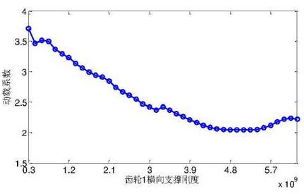
The center support stiffness is selected according to the allowable deflection of the drive shaft. The center support stiffness meets the requirements from 1/20 of the initial stiffness to 2 times of the initial stiffness, with the interval of 1/20 of the initial stiffness.The transverse support stiffness of the gear is within the range.The natural frequency of the derived linear system also varies when the stiffness of the central support varies.

The dynamic load coefficient varies with the stiffness of the center support as shown in the figure.From a qualitative point of view, with the increase of the stiffness of the center support, the dynamic load coefficient first decreases and then increases.When the transverse support stiffness of the gear is X, the dynamic load coefficient reaches the maximum value.Combining with the natural frequency of the derived linear system, the engagement frequency is close to the sixth natural frequency of the system and the system resonates.

When the lateral support stiffness of the gear wheel is 3 x 10⁸N/m, the dynamic load coefficient of the system reaches the minimum value.With the further increase of support stiffness, the dynamic load coefficient gradually increases, which is mainly due to the third natural frequency of the system gradually increasing and approaching the engagement frequency, thus causing the resonance of the system.The above analysis shows that the central support stiffness of the gear has a significant influence on the dynamic load of the gear. With the change of the central support stiffness, the natural frequency of the system also changes. When the natural frequency of any order approximates the meshing frequency of the gear, the dynamic load is larger.It can be seen from the analysis results of dynamic load coefficient varying with engine speed that the meshing frequency and its frequency multiplication should be avoided as close as possible to any natural frequency when designing gear drive system.

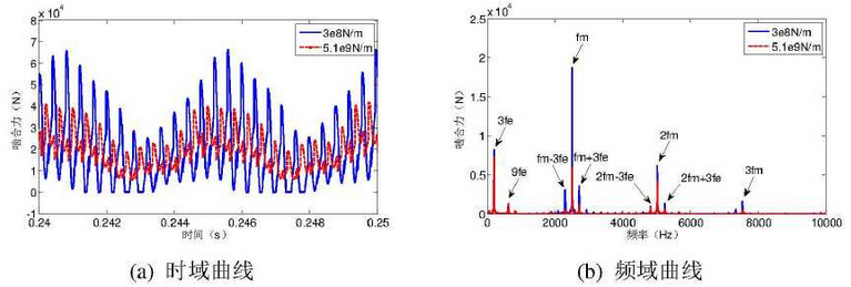
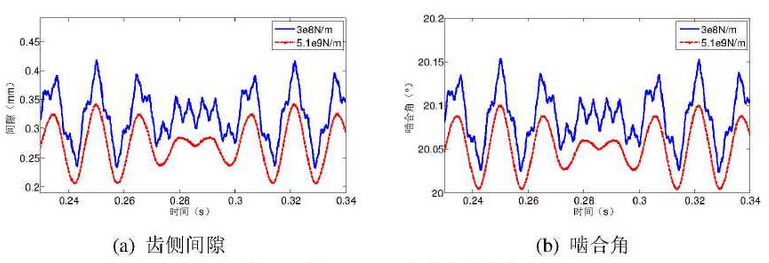
The time-domain and frequency-domain curves of meshing force for maximum and minimum dynamic load coefficient are given.From the point of view of time domain, when the dynamic load coefficient is the maximum, the gear will lose teeth (meshing force is equal to 0), while when the dynamic load coefficient is the minimum, the gear will always keep meshing state.In frequency domain, the corresponding amplitude of meshing frequency at the maximum dynamic load coefficient is significantly larger than that at the minimum dynamic load coefficient.The time-domain curves of tooth-side clearance and engagement angle at the maximum and minimum dynamic load coefficient are shown in the figure. It can be seen from the graph that the tooth-side clearance and engagement angle at the maximum dynamic load coefficient are always greater than those at the minimum dynamic load coefficient.
