Cylindrical gear transmission is one of the most widely used power transmission mechanisms. In gear transmission, due to manufacturing and installation errors, as well as elastic deformation, the load is unevenly distributed along the tooth width direction, resulting in adverse phenomena such as meshing misalignment, meshing impact, and noise, which can easily cause local gear tooth breakage. The tooth profile modification can obtain drum shaped gear teeth, which can evenly distribute stress during gear meshing, reduce meshing offset load, and make gear tooth wear uniform, reduce vibration and noise during gear meshing transmission, and improve gear meshing transmission performance. In terms of tooth profile modification, use high-order polynomial form to perform topological modification on gears on machine tools; Wang Shaojie et al. [9] proposed using multi axis linkage to perform tooth profile modification on gears on honing wheels. They proposed a method of using diamond dressing wheels with the same tooth surface as the target gear for gear modification. They also proposed using a conical grinding wheel with axial stroke point contact to grind the gear shaping cutter and topological modification of the helical gear tooth surface for tooth profile modification. Based on the principle of spatial meshing, a mathematical model for forming and grinding tooth profile modification was established, and the correctness of the model was verified through the helical gear drum shape modification gear. The motion of tooth profile modification through gear grinding technology is complex, and the accuracy is difficult to ensure. The grinding wheel needs to move along the tooth width direction, resulting in low grinding efficiency. gear To improve the efficiency of gear grinding and tooth profile modification,… In terms of accuracy, this article proposes a new grinding method that can achieve tooth profile modification, gear and verifies this method through simulation using Vericut. At the same time, the meshing characteristics of the simulated gears are analyzed, and a control method for drum shape is provided.
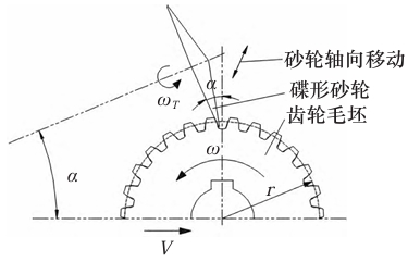
The principle of generating teeth with a butterfly shaped grinding wheel
At present, the main method for grinding teeth is to use a butterfly shaped grinding wheel to develop and grind the tooth surface, based on the grinding principle. To grind the involute tooth profile,gear the tooth blank needs to undergo generating motion, i.e. V= ω· r. Where V is the speed of tooth blank movement, ω Is the speed of the gear blank, and r is the radius of the indexing circle. Grinding wheel according to angular velocity ω When T rotates, the grinding wheel forms a grinding plane to grind the tooth surface. At this time, the grinding wheel moves in a straight line along the axis of the tooth blank, which is intermittent machining in the tooth width direction. The efficiency of gear grinding is low,gear which affects the grinding accuracy.
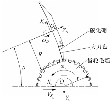
The principle of oblique installation grinding disc for grinding teeth
A new gear grinding method using oblique mounting grinding discs is proposed based on the problems of generating grinding with butterfly shaped grinding wheels. By sintering cubic boron carbide on the grinding disc, the tooth surface is ground with a full tooth width, and the installation angle of the grinding disc is θ, The radius of the grinding disc is R, gear and it can be adjusted according to the required tooth profile modification to grind gears suitable for different occasions. The gear grinding process involves adjusting the grinding disc to ensure that the contact angle between the grinding disc and the tooth surface is the gear pressure angle α。 To grind the involute tooth profile, the tooth blank also needs to undergo generating motion, i.e., where is the speed of tooth blank movement, is the speed of tooth blank rotation, and is the radius of the dividing circle. When the grinding disc is installed at an angle,gear the grinding trajectory is a conical surface, and the full tooth width is used to grind the tooth surface, forming micro drum teeth and achieving tooth alignment modification; When the installation angle of the grinding disc and the grinding trajectory are flat, it is impossible to achieve tooth profile correction.gear When grinding, ensure that the centerline of the tooth width of the blank is at the same height as the center of the grinding disc, and the machined micro drum gear tooth surface of the cylindrical gear will be a symmetrical micro drum shape. Otherwise, the tooth surface will be an asymmetric micro drum shape.
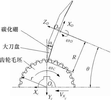
Model of oblique installation grinding disc gear grinding device
The grinding device for grinding the right tooth surface of the gear is achieved through a indexing turntable and a longitudinal slide rail for generative grinding. When grinding the left tooth surface, gear the grinding disc needs to be symmetrically placed.
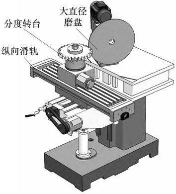
Using SolidWorks to establish gear blanks and machining device models, and importing them into Vericut, the sintered boron carbide on the rotating grinding disc forms a grinding cone surface during machining to grind micro drum shaped gears.
Processing simulation
After setting the machining parameters reasonably,gear import the CNC program for gear simulation machining. During the machining process, the grinding disc rotates rapidly to produce micro convex tooth surfaces. After processing and simulation, micro drum gear teeth cylindrical gears were obtained. When the center line of the tooth width of the blank is at the same height as the center of the grinding disc, the tooth surface after grinding is a symmetrical micro drum shape,gear and the tooth thickness at the center line of the tooth width is slightly greater than the tooth thickness at the gear end face, forming a micro drum shaped gear tooth.
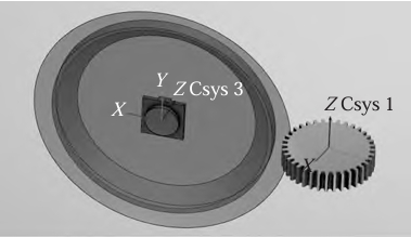
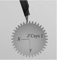
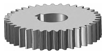
Simulation model analysis
In order to obtain the contact characteristics of cylindrical gears after grinding, the meshing characteristics of the gears after grinding are analyzed. Accurately assemble the gear pair based on its meshing conditions, and use interference inspection tools to perform interference analysis on the tooth surface of the gear pair.gear The analysis results show that the contact area of the drum gear is mainly in the middle part, and the stress in the middle of the tooth surface is greater than the stress at the tooth end. This can effectively improve the uneven load distribution along the tooth width direction caused by errors, elastic deformation, and other reasons during gear transmission, gear effectively reduce the bending stress at the root of the tooth at both ends of the gear, reduce gear meshing bias, improve the meshing performance of the gear, reduce gear transmission noise, and increase the gear bearing capacity.
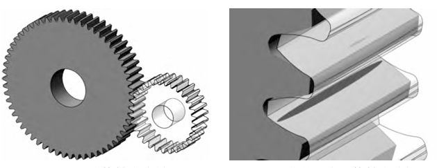
Epilogue
The method of grinding cylindrical gears using a tilted grinding disc was proposed for the first time. Based on the grinding principle, a simulation model of the processing device was established. Vericut was used to achieve the simulation of gear processing and analyze the meshing characteristics of the simulated gears. A control method for the drum quantity was proposed, and the following conclusions were drawn:
(1) Propose a method of grinding cylindrical gears using an inclined grinding disk. gear By sintering boron carbide on the inclined grinding disk, the cylindrical gears are ground across the full tooth width, effectively improving the gear grinding efficiency while achieving tooth profile modification. The depth of the middle of the tooth groove is slightly greater than that of the two ends. When the grinded cylindrical gear pair is meshed, the contact area is mainly in the middle region of the tooth surface, with less contact at both ends, effectively reducing the bending force at the root of the teeth at both ends of the gear, and reducing the gear meshing bias load.
(2) A method for controlling the amount of drum deformation during grinding cylindrical gears is presented. The amount of drum deformation is determined by the installation angle of the grinding disc, the gear modulus, the tooth width, and the radius of the grinding disc. In practical processing, the amount of drum deformation of the gear teeth is adjusted by adjusting the installation angle of the grinding disc.
