
In my extensive experience with gear manufacturing, particularly in hobbing spiral gears, I have encountered a persistent issue known as “tooth disordering” when machining spiral gears with more than 100 teeth and prime-number tooth counts on differential hobbing machines. This problem arises because multiple passes are often required to achieve full tooth depth, leading to misalignment during rapid tool retraction between cuts. The phenomenon disrupts the precise meshing relationship between the hob and the workpiece, resulting in scrap parts and reduced efficiency. Through careful analysis, I have identified the root cause and developed a reliable method to eliminate this issue, which I will elaborate on in this article, focusing on the intricacies of spiral gear production.
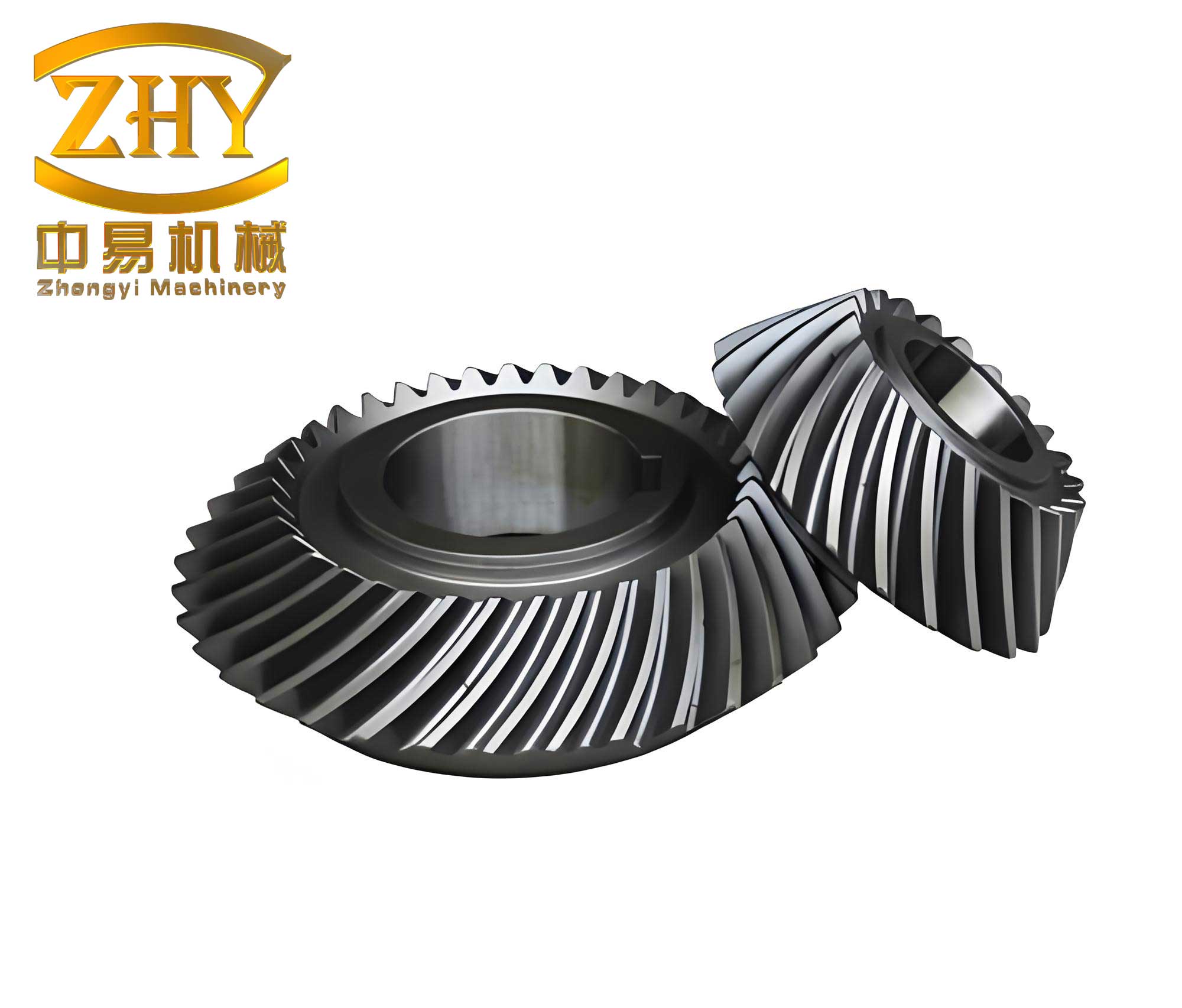
The core of the problem lies in the differential transmission chain of the hobbing machine. When machining spiral gears with prime-number teeth above 100, it is common to adjust the tooth count Z by a small increment ΔZ (less than 1) to facilitate the selection of indexing change gears. This adjustment introduces an additional rotational component that must be compensated by the differential system. Specifically, the differential chain must account for two factors: the supplementary rotation due to the spiral angle β of the spiral gear, and the extra rotation caused by ΔZ. However, during rapid tool retraction after a cut, the machine typically maintains only the helical motion (where the worktable rotates once as the hob moves one lead distance T) without indexing. If the same differential change gears are used for retraction as for cutting, the relative positional relationship between the hob and the gear teeth is disrupted, leading to the “tooth disordering” effect. This is particularly critical in spiral gear manufacturing, where precision is paramount for smooth operation and load distribution.
To address this, I explored several approaches. One simple method involves slowly retracting the hob in the reverse direction using the same transmission chains after a cut, without disengaging the workpiece. While this prevents tooth disordering, it doubles the processing time, as retraction takes as long as the cutting pass, significantly reducing efficiency in spiral gear production. Another common practice relies on operator skill to realign the tool after rapid retraction, but this is error-prone and often leads to rejects. Therefore, I devised a more systematic solution: swapping the differential change gears specifically for rapid tool retraction. This method has been proven effective over years of application in machining high-tooth-count spiral gears.
To illustrate, let’s consider a Y3150-type hobbing machine as a representative model. The transmission system involves calculating change gears for both cutting and retraction phases. The key equations revolve around the differential gear ratio, which ensures correct tooth formation in spiral gears. Below, I present the formulas and tables that summarize the calculations, emphasizing the role of spiral gear parameters.
During cutting, the differential change gear ratio idiff is given by:
$$ i_{diff} = \pm \frac{a}{b} \cdot \frac{c}{d} = \pm \frac{25\pi}{T} \left( \frac{\sin \beta}{m_n Z} \right) \pm \frac{\Delta Z}{Z} $$
Where:
- Z is the number of teeth on the spiral gear (with ΔZ added or subtracted for prime-number adjustments).
- β is the spiral angle of the gear, critical for defining the helix in spiral gears.
- mn is the normal module of the spiral gear.
- T is the lead of the spiral gear, calculated as T = π mn Z / sin β.
- The ± signs depend on the hand of the spiral gear and hob rotation; I will detail this later.
When the hob moves vertically by one lead T, the supplementary rotation provided by the differential system to the workpiece must account for both spiral angle compensation and ΔZ effects. This can be expressed as:
$$ \Delta \theta = \pm \frac{T}{p} \cdot \frac{1}{i_{diff}} \pm \frac{\Delta Z}{Z} $$
Here, p represents the hob lead, and the terms ensure precise tooth engagement in spiral gears.
For rapid retraction, we need to adjust the differential change gears to maintain alignment. Two scenarios can be considered, each with specific formulas for the retraction differential gear ratio idiff_retract:
| Scenario | Conditions | Retraction Differential Gear Ratio Formula | Application Notes for Spiral Gears |
|---|---|---|---|
| 1 | Worktable rotates, hob stationary during retraction | $$ i_{diff\_retract} = \pm \frac{Z}{k} \cdot \frac{T}{p} $$ | Preferred for safety; disengage hob rotation and use quick-retract lever. |
| 2 | Hob rotates, worktable stationary during retraction | $$ i_{diff\_retract} = \pm \frac{k}{Z} \cdot \frac{p}{T} $$ | Less common; requires careful handling to avoid errors in spiral gear indexing. |
In these formulas, k is the number of starts on the hob, and the ± signs are determined as follows:
- Assume a right-hand hob is used. If the indexing gear formula uses Z + ΔZ, the first term in the differential equation takes a “+” sign; otherwise, use “–”.
- If the spiral gear and hob have the same hand (e.g., both right-hand spiral gears), the second term uses “+”; otherwise, use “–”.
- A positive result indicates the differential motion adds to the worktable rotation, while negative means it subtracts, ensuring proper tooth tracking in spiral gears.
To provide a clearer summary, here is a table of key parameters for spiral gear hobbing on a Y3150 machine:
| Parameter | Symbol | Typical Range for Spiral Gears | Impact on Tooth Disordering |
|---|---|---|---|
| Number of Teeth | Z | >100, prime numbers | High; requires ΔZ adjustment |
| Spiral Angle | β | 10° to 45° | Critical for differential compensation |
| Normal Module | mn | 1–10 mm | Affects lead T calculations |
| Hob Starts | k | 1–4 | Influences gear ratios |
| Lead | T | $$ T = \frac{\pi m_n Z}{\sin \beta} $$ | Core to helical motion in spiral gears |
Through theoretical derivation and practical verification, I have confirmed that the above formulas yield accurate results for spiral gears. Specifically, Scenario 1 (worktable rotation during retraction) is recommended for its safety and convenience. To implement this, after cutting, disengage the hob rotation, set the quick-retract lever, and use the retraction differential gears calculated as per the table. This prevents tooth disordering without sacrificing efficiency, a crucial advance for high-precision spiral gear manufacturing.
However, machining spiral gears with over 100 teeth and prime numbers involves complexities beyond mere calculations. Based on my experience, several precautions are essential:
- The differential gear ratios idiff and idiff_retract must be precise to at least five decimal places to ensure accuracy in spiral gear tooth profiles. Use calibrated change gears and verify with test cuts if possible.
- Before swapping change gears, always position the machine handles to the required settings to avoid backlash or misalignment that could damage spiral gear teeth.
- During gear changes, handle the differential passive shaft gently; if teeth clash, rotate slightly by a tooth or two to adjust clearance, but avoid forced movements.
- After installing retraction differential gears, never operate the machine in cutting mode during rapid retraction, and vice versa. Engage the automatic feed clutch only when using cutting gears to prevent mechanical issues.
- Do not alter the feed rate mid-process without recalculating differential gears, as this changes the lead relationship and can induce errors in spiral gear generation.
- Regularly maintain the hobbing machine, especially the differential assembly, to minimize wear that might affect spiral gear quality.
In practice, I have applied this method to various spiral gear projects, from industrial machinery to automotive transmissions. For example, when hobbing a spiral gear with Z = 101, β = 20°, mn = 2 mm, and using a single-start hob (k = 1), the calculations proceed as follows. First, compute the lead T:
$$ T = \frac{\pi \times 2 \times 101}{\sin 20°} = \frac{634.28}{0.342} \approx 1854.5 \text{ mm} $$
Assuming ΔZ = 0.5 is added for indexing, the cutting differential ratio for a right-hand spiral gear matching the hob is:
$$ i_{diff} = + \frac{25\pi}{1854.5} \left( \frac{\sin 20°}{2 \times 101} \right) + \frac{0.5}{101} \approx 0.0423 + 0.00495 = 0.04725 $$
For retraction using Scenario 1, the retraction ratio is:
$$ i_{diff\_retract} = + \frac{101}{1} \cdot \frac{1854.5}{\pi \times 2} \approx 101 \times 295.3 = 29825.3 $$
This high ratio underscores the need for precise gear selection. In actual setups, I use compound change gears to approximate these values, ensuring tooth alignment in the spiral gear is maintained after rapid retraction.
Moreover, the importance of spiral gears in modern engineering cannot be overstated. They offer smoother engagement, higher load capacity, and reduced noise compared to spur gears, making them ideal for applications like wind turbines, aerospace systems, and precision instruments. Thus, refining hobbing techniques for large prime-number spiral gears contributes significantly to industrial advancement. My method not only eliminates tooth disordering but also enhances repeatability, allowing for batch production of spiral gears with consistent quality.
To further illustrate the process, here is a step-by-step summary in table form:
| Step | Action | Key Formulas for Spiral Gears | Expected Outcome |
|---|---|---|---|
| 1 | Calculate workpiece parameters: Z, β, mn | $$ T = \frac{\pi m_n Z}{\sin \beta} $$ | Determine lead for spiral gear |
| 2 | Select ΔZ for indexing (if needed) | Typically ΔZ < 1 | Facilitate change gear selection |
| 3 | Compute cutting differential gear ratio | $$ i_{diff} = \pm \frac{25\pi}{T} \left( \frac{\sin \beta}{m_n Z} \right) \pm \frac{\Delta Z}{Z} $$ | Set up machine for initial cut on spiral gear |
| 4 | Perform first cutting pass | Monitor feed and alignment | Form partial tooth depth on spiral gear |
| 5 | Calculate retraction differential gear ratio | $$ i_{diff\_retract} = \pm \frac{Z}{k} \cdot \frac{T}{p} $$ (Scenario 1) | Prepare for rapid tool retraction |
| 6 | Swap to retraction gears, retract hob quickly | Disengage hob rotation if using Scenario 1 | Maintain tooth position in spiral gear |
| 7 | Revert to cutting gears for next pass | Ensure all handles are correctly positioned | Continue hobbing without disordering |
| 8 | Repeat until full depth is achieved | Check tooth profile periodically | Complete spiral gear with high accuracy |
In conclusion, the method of changing differential change gears for rapid retraction effectively eliminates tooth disordering in hobbing spiral gears with over 100 teeth and prime-number counts. This approach balances efficiency and precision, crucial for high-volume spiral gear production. By adhering to the formulas and precautions outlined, manufacturers can achieve reliable results, reducing scrap rates and enhancing productivity. The spiral gear, with its unique helical teeth, demands meticulous attention during machining, and this solution addresses a common pitfall in differential hobbing machines. As technology evolves, further refinements may emerge, but the principles remain rooted in understanding the interplay between differential compensation and spiral gear geometry. I encourage practitioners to test this method in their own setups, as it has consistently proven valuable in my work with complex spiral gear systems.