
In the realm of power transmission, particularly for automotive drive axles, hypoid gears are indispensable components. Their ability to transmit motion and power between non-intersecting, crossed axes makes them superior to other bevel gear types in providing higher torque capacity, smoother operation, and the ability to lower the vehicle’s center of gravity. Consequently, the manufacturing quality of hypoid gears directly impacts the performance, durability, and noise characteristics of the final vehicle. The pursuit of higher strength, better fatigue resistance, and more precise tooth geometry has driven continuous innovation in their manufacturing processes.
Traditional manufacturing of hypoid gears, especially the larger ring gear, often involves a sequence of forging, rough machining, and heat treatment followed by final grinding. While effective, this process chain is lengthy and costly. A promising alternative is the application of cold rotary forging, also known as orbital forging or axial roll forming, as a finishing operation. This incremental forming technique applies localized, progressive pressure to the workpiece, resulting in significant advantages such as reduced forming loads, improved surface finish, and enhanced material strength due to work hardening. For hypoid gears, a specialized cold rotary forging scheme has been proposed where a trapezoidal die, mimicking the action of a grinding wheel, plastically forms the tooth flank through localized line contact. This method offers a compelling route to streamline production. However, a critical challenge hindering its widespread industrial adoption is the limited service life of the forging die. The high contact stresses and severe friction experienced by the die surface during the forming of hard gear materials lead to rapid failure through mechanisms like fatigue, wear, or plastic deformation. Frequent die replacement skyrockets production costs and undermines the efficiency gains of the process. Therefore, accurate prediction and strategic enhancement of die life are paramount for the economic viability of cold rotary forging for hypoid gears.
This article delves into the methodology for predicting die life in the cold rotary forging of hypoid gears and explores the optimization of process parameters to maximize it. The core of our approach lies in coupling advanced numerical simulation with established fatigue life estimation models. We begin by establishing a thermo-mechanically coupled finite element model to simulate the complex, three-dimensional metal flow and the resulting stress-strain fields within the die. From this simulation, we extract critical data—specifically, the stress history at the most vulnerable point on the die, typically where stress concentration is highest. We then employ the local stress-strain method, a well-regarded approach in fatigue analysis, to translate these stress values into an estimated number of forging cycles before die failure. The model accounts for the temperature-dependent material properties of the die steel, as the process generates heat through plastic deformation and friction. Armed with this predictive capability, we systematically investigate the influence of key process parameters: the upper die rotation speed, the upper die tilt angle, and the friction factor at the die-workpiece interface. By analyzing how each parameter affects the die’s stress state and, consequently, its predicted life, we can identify optimal operating windows. Our goal is to move beyond trial-and-error and provide a scientifically grounded framework for designing durable and cost-effective cold rotary forging processes for high-precision hypoid gears.
The Principle of Cold Rotary Forging for Hypoid Gears
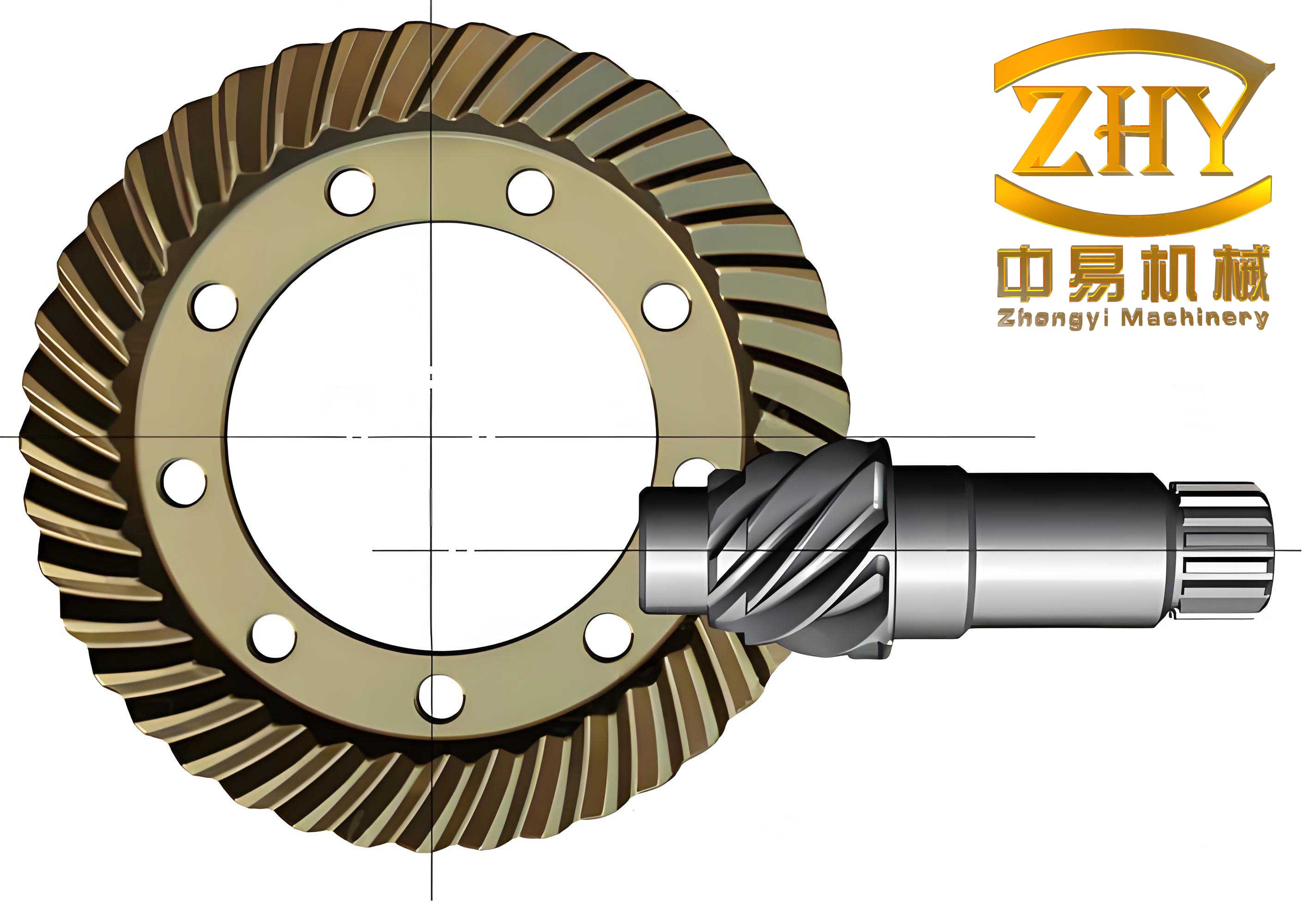
The cold rotary forging process for finishing hypoid gears represents a significant departure from conventional closed-die forging. Its uniqueness stems from the specific kinematic motion of the die and the targeted, incremental nature of deformation. In this dedicated scheme, the workpiece is the pre-formed hypoid gear blank, typically made from case-hardening steel like 20CrMnTiH. The forming die is not a full-tooth cavity but rather a simple, rotating trapezoidal tool. The die executes a complex, dual motion: it revolves around the main machine axis (orbital motion) while simultaneously rotating about its own geometric axis (spinning motion). The die’s axis is also tilted at a fixed angle relative to the machine spindle, known as the tilt or swing angle. This combined orbital and spinning motion causes the die to make successive, localized contact with the tooth flank surface of the stationary gear blank.
The deformation is highly localized. As the die orbits, only a small area of the tooth flank is under pressure at any given instant. This area of contact progressively sweeps across the entire tooth profile from one end to the other, gradually imparting the final, precise geometry through plastic deformation. This incremental approach drastically reduces the instantaneous forming force required compared to a single-stroke process that deforms the entire tooth simultaneously. After one tooth is completely formed, an indexing mechanism rotates the gear blank precisely to bring the next tooth into position under the die, and the process repeats. The key advantages of this method for hypoid gears include the ability to achieve excellent surface finish and dimensional accuracy, induce beneficial compressive residual stresses, and streamline the process chain by potentially eliminating a final grinding operation. However, the success of this technique hinges entirely on the durability of the relatively simple yet critically loaded trapezoidal die, making life prediction and optimization essential.
Modeling for Die Life Prediction: Integrating Simulation and Fatigue Theory
Predicting the life of a die in a complex process like cold rotary forging requires a multi-step, integrated approach. We cannot rely solely on analytical calculations due to the intricate geometry of hypoid gears and the non-linear material behavior. Therefore, our methodology is built on two pillars: high-fidelity finite element analysis (FEA) to obtain the die’s response, and the application of fatigue life estimation models to interpret that response.
Finite Element Simulation Setup
To accurately capture the stresses without prohibitive computational cost, we construct a three-dimensional, thermo-mechanically coupled, elastic-plastic finite element model. The gear blank is modeled as a deformable body using a subset of teeth (e.g., a 10-tooth sector) to balance accuracy and efficiency. The material model for the gear steel includes its strain-hardening and thermal softening characteristics. The die, typically made from a hot-work tool steel like 4Cr5MoSiV1 (H13), is modeled as a rigid body since its hardness and stiffness are orders of magnitude greater than the deforming workpiece; this simplification significantly reduces computation time. The interface between the die and the workpiece is governed by a shear friction model, defined by a friction factor ‘m’. The mesh is refined in the deformation zone where high gradients of stress and strain are expected, while coarser elements are used elsewhere. The simulation solves for the transient development of stress, strain, and temperature throughout the forming cycle of a single tooth.
The Local Stress-Strain Approach for Fatigue Life Estimation
The fatigue life of the die is primarily governed by the cyclic stress-strain history at the most critical location, which is usually a point of stress concentration such as the die’s tooth tip or a fillet radius. We use the local stress-strain method, which correlates the strain amplitude at the critical point to the number of cycles to failure. The foundational relationship is described by the Manson-Coffin equation, which separates total strain into elastic and plastic components:
$$
\frac{\Delta \varepsilon}{2} = \frac{\Delta \varepsilon_e}{2} + \frac{\Delta \varepsilon_p}{2} = \varepsilon’_f (2N)^c + \frac{\sigma’_f – \sigma_m}{E} (2N)^b
$$
where:
• $\Delta \varepsilon$ is the total strain range.
• $\Delta \varepsilon_e$ and $\Delta \varepsilon_p$ are the elastic and plastic strain ranges, respectively.
• $N$ is the number of cycles to failure (die life).
• $\varepsilon’_f$ is the fatigue ductility coefficient.
• $c$ is the fatigue ductility exponent.
• $\sigma’_f$ is the fatigue strength coefficient (often approximated by the material’s ultimate or yield strength at the operating temperature).
• $\sigma_m$ is the mean stress ($\sigma_{max} – \sigma_{min})/2$.
• $E$ is the Young’s modulus.
• $b$ is the fatigue strength exponent.
For the die steel under cold forging conditions, the stresses, although high, typically remain in the elastic range for the die material itself. This means the plastic strain component $\Delta \varepsilon_p$ is negligible. When $\Delta \varepsilon_e \gg \Delta \varepsilon_p$, the life estimation simplifies considerably. We can use a derived formula, such as the Dowling formula, which focuses on the elastic strain (stress) component. The number of cycles to failure $N_e$ can be estimated as:
$$
\frac{1}{N_e} = 2 \left[ \frac{\Delta \varepsilon_e E}{2(\sigma’_f – \sigma_m)} \right]^{-1/b}
$$
Since $\Delta \varepsilon_e E = \Delta \sigma$, where $\Delta \sigma$ is the stress range ($\sigma_{max} – \sigma_{min}$) obtained directly from the FEA, the formula becomes practical for computation. The stress range $\Delta \sigma$ and mean stress $\sigma_m$ are extracted from the simulated cyclic stress history at the critical point. The fatigue strength coefficient $\sigma’_f$ is taken as the temperature-dependent yield stress of the die material. The fatigue strength exponent $b$ is a crucial material constant; for tool steels under high-cycle forging conditions, a corrected value (e.g., $b = -0.08$) is used to account for factors like surface finish and size effect, extending the model’s applicability.
This integrated framework allows us to move from a simulated stress output to a quantitative life prediction. We first run the FEA for a given set of process parameters, identify the point of maximum equivalent (von Mises) stress on the die, record its $\sigma_{max}$ and $\sigma_{min}$ (usually zero when the die loses contact), and calculate the corresponding die temperature. We then plug these values, along with the temperature-corrected material properties, into the life estimation model to calculate $N$. This $N$ represents the predicted number of forging cycles for that specific tooth-engaging section of the die. Since the die is annular and much larger than a single tooth, its total service life is this value multiplied by the number of distinct contact zones around its circumference.
Parametric Analysis and Optimization of Process Parameters
With the established prediction model, we can systematically investigate how the three primary controllable process variables affect die life in the cold rotary forging of hypoid gears. The goal is to understand the influence trends and identify optimal parameter combinations. We employ a single-factor analysis method, varying one parameter at a time while holding the others constant, and observe the change in predicted die life. The key parameters are:
- Upper Die Rotation Speed (n): The orbital speed of the die, measured in revolutions per minute (rpm).
- Upper Die Tilt Angle (γ): The angle between the die axis and the machine spindle, measured in degrees (°).
- Friction Factor (m): A dimensionless parameter (0 ≤ m ≤ 1) representing the shear friction condition at the die-workpiece interface.
The following sections present the findings from this parametric study, with data summarized in tables.
1. Influence of Upper Die Rotation Speed (n)
Holding the tilt angle (γ=6°) and friction factor (m=0.14) constant, we simulated the process for a range of rotation speeds. The results, including the die temperature at the critical point, the temperature-adjusted yield strength ($\sigma’_f$), the maximum stress ($\sigma_{max}$), and the calculated die life ($N$), are presented below.
| Rotation Speed, n (rpm) | Die Temp. (°C) | $\sigma’_f$ (MPa) | $\sigma_{max}$ (MPa) | $\sigma_{min}$ (MPa) | $\Delta \sigma$ (MPa) | $\sigma_m$ (MPa) | Die Life, N (cycles) |
|---|---|---|---|---|---|---|---|
| 20 | 208 | 1429 | 950 | 0 | 950 | 475 | 12,056 |
| 30 | 239 | 1408 | 940 | 0 | 940 | 470 | 10,941 |
| 40 | 254 | 1395 | 920 | 0 | 920 | 460 | 14,295 |
| 60 | 273 | 1377 | 910 | 0 | 910 | 455 | 13,554 |
| 120 | 295 | 1352 | 900 | 0 | 900 | 450 | 11,626 |
| 240 | 329 | 1211 | 890 | 0 | 890 | 445 | 1,280 |
| 480 | 344 | 1190 | 870 | 0 | 870 | 435 | 1,477 |
Analysis of the data reveals a non-linear and complex relationship between rotation speed and die life. The life initially decreases slightly, then reaches a peak of approximately 14,300 cycles at n = 40 rpm. Within the medium-speed range (40-120 rpm), the life remains relatively high. However, a dramatic drop occurs as speed increases beyond 120 rpm. At 240 rpm and 480 rpm, the predicted life plummets to around 1,300 cycles. This drastic reduction is primarily attributed to the significant increase in die temperature at high speeds. The higher strain rate and increased frictional work lead to more adiabatic heating, which softens the die material (lowering $\sigma’_f$). Although the maximum contact stress ($\sigma_{max}$) shows a slight decreasing trend, the severe reduction in material strength dominates, leading to a much lower effective fatigue resistance. Therefore, for the cold rotary forging of hypoid gears, operating at a moderate rotation speed (e.g., 40-60 rpm) is crucial for achieving a balance between productivity and die longevity.
2. Influence of Upper Die Tilt Angle (γ)
Holding the rotation speed (n=120 rpm) and friction factor (m=0.14) constant, we varied the tilt angle. The simulation results are summarized in the table below.
| Tilt Angle, γ (°) | Die Temp. (°C) | $\sigma’_f$ (MPa) | $\sigma_{max}$ (MPa) | $\sigma_{min}$ (MPa) | $\Delta \sigma$ (MPa) | $\sigma_m$ (MPa) | Die Life, N (cycles) |
|---|---|---|---|---|---|---|---|
| 1 | 354 | 1176 | 870 | 0 | 870 | 435 | 1,106 |
| 2 | 332 | 1207 | 890 | 0 | 890 | 445 | 1,183 |
| 4 | 315 | 1230 | 910 | 0 | 910 | 455 | 1,109 |
| 6 | 295 | 1352 | 900 | 0 | 900 | 450 | 11,626 |
| 10 | 286 | 1362 | 890 | 0 | 890 | 445 | 17,496 |
| 15 | 305 | 1244 | 880 | 0 | 880 | 440 | 3,057 |
| 25 | 312 | 1234 | 890 | 0 | 890 | 445 | 1,987 |
The influence of the tilt angle is profound and non-monotonic. At very small angles (1° to 4°), the die life is extremely low (around 1,100 cycles). This is likely because a small tilt angle results in a larger instantaneous contact area, potentially leading to higher forming forces and less favorable stress distribution. As the angle increases to 6°, there is a step-change improvement, with life jumping to over 11,600 cycles. The optimal life is achieved at a tilt angle of around 10°, yielding a predicted life of nearly 17,500 cycles. At this angle, the contact mechanics and the incremental deformation pattern likely create an optimal balance, reducing peak stress and improving material flow. Further increasing the angle to 15° and 25° causes the life to drop sharply again. Larger angles may increase the sliding velocity component, leading to higher frictional heating and altered stress states. This analysis clearly indicates that the tilt angle is a highly sensitive parameter for the cold rotary forging of hypoid gears, and an optimal window exists near 10° for the studied configuration.
3. Influence of Friction Factor (m)
Holding the rotation speed (n=120 rpm) and tilt angle (γ=6°) constant, we examined the effect of interfacial friction. The results are presented in the following table.
| Friction Factor, m | Die Temp. (°C) | $\sigma’_f$ (MPa) | $\sigma_{max}$ (MPa) | $\sigma_{min}$ (MPa) | $\Delta \sigma$ (MPa) | $\sigma_m$ (MPa) | Die Life, N (cycles) |
|---|---|---|---|---|---|---|---|
| 0.05 | 153 | 1450 | 990 | 0 | 990 | 495 | 6,729 |
| 0.10 | 256 | 1393 | 950 | 0 | 950 | 475 | 6,912 |
| 0.14 | 295 | 1352 | 900 | 0 | 900 | 450 | 11,626 |
| 0.30 | 332 | 1207 | 890 | 0 | 890 | 445 | 1,183 |
| 0.40 | 361 | 1166 | 900 | 0 | 900 | 450 | 415 |
| 0.50 | 371 | 1152 | 900 | 0 | 900 | 450 | 312 |
| 0.60 | 397 | 1116 | 920 | 0 | 920 | 460 | 85 |
The friction factor exhibits a critical and highly non-linear impact on die life. At very low friction (m=0.05, 0.10), the life is at a moderate level (~6,800 cycles). Interestingly, as friction increases to 0.14, the life peaks at 11,626 cycles. This suggests that a certain level of friction might be beneficial, possibly by altering the metal flow to produce a more uniform stress distribution or by affecting the heat generation balance. However, this beneficial window is narrow. Any further increase in friction proves catastrophic for die life. As m rises to 0.30, life collapses to about 1,180 cycles. For m ≥ 0.40, the life is measured in only hundreds or even tens of cycles. The primary reason is the extreme temperature rise caused by high frictional work, which dramatically softens the die steel (note the drop in $\sigma’_f$ from 1450 MPa at m=0.05 to 1116 MPa at m=0.60). This thermal softening effect overwhelms any changes in the stress amplitude. The clear conclusion is that maintaining excellent lubrication to control the friction factor is absolutely essential for the cold rotary forging of hypoid gears. An optimal, moderate friction level (around 0.14 in this study) should be targeted through lubricant selection and application.
Synthesis and Determination of Optimal Process Parameters
Based on the single-factor analysis, we can synthesize the findings to propose an optimal parameter set for maximizing die life in the cold rotary forging of hypoid gears. The individual optimal points from the studies were:
• Rotation Speed (n): ~40 rpm
• Tilt Angle (γ): ~10°
• Friction Factor (m): ~0.14
We then run a final simulation with this combined parameter set to verify the synergistic effect. The results are presented below.
| n (rpm) | γ (°) | m | Die Temp. (°C) | $\sigma’_f$ (MPa) | $\sigma_{max}$ (MPa) | $\sigma_{min}$ (MPa) | $\Delta \sigma$ (MPa) | $\sigma_m$ (MPa) | Die Life, N (cycles) |
|---|---|---|---|---|---|---|---|---|---|
| 40 | 10 | 0.14 | 241 | 1406 | 910 | 0 | 910 | 455 | 21,464 |
The result is compelling. The optimized parameter combination yields a predicted die life of 21,464 cycles, which is significantly higher than the lives observed in most of the single-factor tests. This represents a substantial improvement, confirming that the parameters interact and that a holistic optimization is necessary. It’s important to recall that this calculated life (N) is for a specific contact zone on the annular die. Given that the die circumference is much larger than the arc length of a single hypoid gear tooth contact patch (approximately 16 times larger in the studied case), the total service life of the die before it needs reconditioning or replacement would be roughly $21,464 \times 16 \approx 343,424$ forging cycles. This translates to the production of a very large number of gears, dramatically improving process economy and productivity.
Conclusion
The successful implementation of cold rotary forging as a finishing process for high-performance hypoid gears critically depends on solving the die life challenge. This article has presented a comprehensive, integrated methodology to address this issue. By combining high-fidelity thermo-mechanical finite element simulation with the established local stress-strain fatigue life estimation method, we can effectively predict the service life of the forming die under specific process conditions. This predictive capability moves the process design from empirical guesswork to a science-based approach.
Our detailed parametric study on the cold rotary forging of hypoid gears revealed the complex, non-linear influence of key process parameters:
• Upper Die Rotation Speed: A moderate speed (~40 rpm) is optimal. Very high speeds cause excessive die heating and material softening, leading to a catastrophic drop in life.
• Upper Die Tilt Angle: This is a highly sensitive parameter. An optimal window exists around 10°, providing a favorable contact condition that minimizes damaging stress concentrations. Both very small and very large angles are detrimental.
• Friction Factor: Control of interfacial friction through lubrication is paramount. While a moderate level (~0.14) can be beneficial, any increase beyond this narrow window causes severe thermal softening and rapid die failure.
The synthesis of these findings led to an optimized parameter set (n=40 rpm, γ=10°, m=0.14), which was predicted to extend the die life to over 21,000 cycles per contact zone—a significant enhancement. When considering the full annular die, this translates to the potential for producing hundreds of thousands of hypoid gears with a single die setup, making the cold rotary forging process highly competitive. This framework provides a powerful tool for engineers to design durable processes, reduce costs, and improve the manufacturing efficiency of essential automotive components like hypoid gears.