
In the transmission systems of rail vehicles, the axle gearbox represents the final assembly in the powertrain chain. It is uniquely positioned on the axle between the wheelsets. A fundamental and challenging characteristic of its application, which distinguishes it from similar gearboxes used in military or other heavy vehicles, is its mounting and support philosophy. The output axle itself serves as the primary structural support for the entire gearbox housing. Consequently, this axle must bear not only the operational torsional and bending loads from the gears but also the significant static weight of the locomotive’s mass. This combined loading induces considerable elastic deformation in the axle. This deformation is not a minor deflection but a substantial displacement that directly impacts the critical meshing alignment of the spiral bevel gears mounted on it.
The primary meshing misalignments caused by this axle deflection include substantial variations in the offset (E) and axial displacements of the pinion and gear (XP, XW). These misalignments are further compounded by inherent random factors present in any mechanical system: manufacturing inaccuracies in the gears and housing, assembly errors, and fluctuating external load conditions. The synergy of systematic axle deformation and these random errors leads to severe edge-loading conditions, concentrated stress peaks, and non-uniform load distribution across the tooth flanks of the spiral bevel gears. This aberrant contact behavior is a primary driver of premature failure modes such as pitting, spalling, and bending fatigue, drastically curtailing the operational life of the gear set.
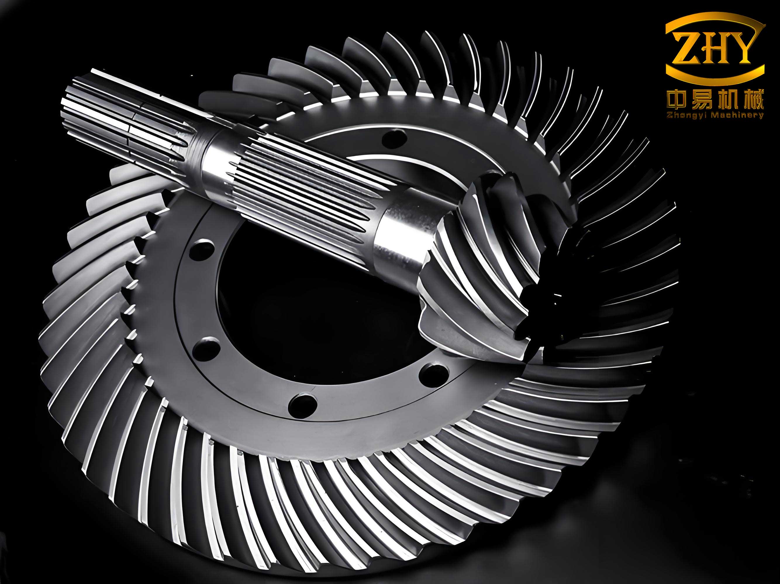
To mitigate these detrimental effects and solve the life expectancy problem, meticulous attention must be paid to the design of the tooth surface geometry. The industry-standard solution is gear micro-geometry optimization, commonly known as gear modification or “Ease-Off” design. The principle is to proactively and intentionally remove minute amounts of material from the ideal conjugate tooth surfaces in a controlled pattern. For spiral bevel gears, this involves both profile and lead modifications. Profile modification, which includes tip relief (removing material near the tooth top) and root relief (removing material near the tooth fillet), is primarily aimed at compensating for deflections and errors that affect the meshing action along the tooth profile, thereby smoothing the transition as teeth engage and disengage to reduce impact and noise. The goal of this comprehensive modification process is to optimize the contact pattern under loaded conditions, distribute contact stress more evenly, minimize transmission error fluctuations, and ultimately enhance the load-carrying capacity and durability of the gear pair. This paper details a systematic study employing advanced design calculation methods, specialized software simulation, and finite element analysis to optimize the modification of spiral bevel gears for an axle gearbox application, with the core objective of significantly improving their bending and contact fatigue life.
Geometric and Operational Parameter Definition
The foundation of any gear analysis lies in its precise geometric definition and the expected service conditions. The subject spiral bevel gears for the axle gearbox are defined by the following key parameters:
| Parameter | Pinion | Gear (Wheel) | Unit |
|---|---|---|---|
| Number of Teeth (z) | 26 | 35 | – |
| Module (mn) | 7.86 | mm | |
| Pressure Angle (α) | 22.5 | deg | |
| Shaft Angle (Σ) | 90 | deg | |
| Mean Spiral Angle (βm) | 35 | deg | |
| Hand of Spiral | Left | Right | – |
| Face Width | To be determined from detailed design | mm | |
The operational profile of the rail vehicle dictates several distinct duty cycles that the gears must endure. These are categorized as follows:
| Duty Cycle | Description & Key Requirement |
|---|---|
| Starting Condition | Maximum starting tractive effort of 130 kN. This is the peak load condition for static strength validation. |
| Low-Speed Traction | Must be capable of starting and operating on a steep gradient of 33‰. Maximum travel speed in this mode is 10 km/h. |
| High-Speed Running | Sustained high-speed operation with a maximum vehicle speed of 160 km/h. This condition emphasizes durability and dynamic load factors. |
Analytical Fatigue Strength Assessment
Prior to micro-geometry optimization, a fundamental fatigue strength analysis was performed according to standardized calculation methods (e.g., ISO 10300, AGMA 2003) to establish baseline safety factors. The core formulas for contact stress and bending stress calculation, along with their corresponding safety factors, are presented below.
Contact Stress and Safety Factor
The calculated contact stress σH at the pitch point is determined by adjusting the nominal contact stress with several application factors:
$$ \sigma_H = \sigma_{H0} \cdot \sqrt{K_A \cdot K_{V} \cdot K_{H\beta} \cdot K_{H\alpha}} $$
Where:
σH0 is the nominal contact stress based on geometry and torque.
KA is the application factor (accounts for external load characteristics).
KV is the dynamic factor (accounts for internal dynamic loads due to pitch errors).
KHβ is the face load factor for contact stress (accounts for load distribution across the face width).
KHα is the transverse load factor for contact stress (accounts for load sharing between simultaneous tooth pairs).
The safety factor against pitting (SH) is then calculated as:
$$ S_H = \frac{\sigma_{Hlim} \cdot Z_{NT} \cdot Z_L \cdot Z_R \cdot Z_V \cdot Z_W \cdot Z_X}{\sigma_H} \geq S_{Hmin} $$
Where:
σHlim is the allowable contact stress number of the material.
ZNT is the life factor for contact stress.
ZL, ZR, ZV are the lubricant film factors (roughness, velocity, viscosity).
ZW is the work hardening factor.
ZX is the size factor for contact stress.
SHmin is the minimum required safety factor.
Bending Stress and Safety Factor
The calculated root bending stress σF is given by:
$$ \sigma_F = \sigma_{F0} \cdot K_A \cdot K_{V} \cdot K_{F\beta} \cdot K_{F\alpha} $$
Where:
σF0 is the nominal tooth root stress.
KFβ is the face load factor for bending stress.
KFα is the transverse load factor for bending stress.
The safety factor against tooth breakage (SF) is calculated as:
$$ S_F = \frac{\sigma_{Flim} \cdot Y_{ST} \cdot Y_{NT} \cdot Y_{\delta rel T} \cdot Y_{R rel T} \cdot Y_X}{\sigma_F} \geq S_{Fmin} $$
Where:
σFlim is the allowable bending stress number of the material.
YST is the stress correction factor (typically 2.0).
YNT is the life factor for bending stress.
Yδ rel T is the relative notch sensitivity factor.
YR rel T is the relative surface condition factor.
YX is the size factor for bending stress.
SFmin is the minimum required safety factor.
Applying these formulas to the defined spiral bevel gears and the starting torque condition yielded the following baseline results:
| Component & Parameter | Pinion | Gear | Unit |
|---|---|---|---|
| Calculated Contact Stress (σH) | 1572.7 | 1580.6 | MPa |
| Contact Safety Factor (SH) | 1.587 | 1.663 | – |
| Calculated Bending Stress (σF) | 220.21 | 336.19 | MPa |
| Bending Safety Factor (SF) | 1.432 | 1.298 | – |
While the safety factors are above a nominal value of 1.0, the bending safety factor for the gear, in particular, is relatively low. More critically, these calculations use idealized, uniform load distribution factors (KHβ, KFβ). The real-world misalignments would significantly worsen these factors, leading to much higher localized stresses and lower effective safety. This underscores the necessity for micro-geometry optimization.
Micro-Geometry Optimization via Tooth Flank Modification
The core of this research involves the systematic modification of the tooth flanks to compensate for the predictable misalignments. The first step was to quantify the misalignments for each critical duty cycle using a comprehensive stiffness model of the system, including the axle, bearings, and housing.
| Duty Cycle | Offset (E) [μm] |
Pinion Axial Displ. (XP) [μm] |
Gear Axial Displ. (XW) [μm] |
Shaft Angle Error (ΔΣ) [μrad] |
|---|---|---|---|---|
| Starting (Peak Torque) | -394.8 | 422.5 | -730.4 | 1255 |
| Low-Speed Traction | -124.0 | 107.6 | -545.0 | 574 |
| Braking | -187.6 | 186.7 | -592.2 | 746 |
| High-Speed Running (Case 1) | -154.1 | 145.2 | -567.6 | 655 |
| High-Speed Running (Case 2) | -136.8 | 123.7 | -554.7 | 609 |
The negative offset indicates a specific direction of axial movement altering the theoretical cone distance. These values, especially the large ones during starting, confirm that misalignment is a major design driver. Using these misalignments as input conditions, a sophisticated Loaded Tooth Contact Analysis (LTCA) was performed using specialized gear design software (MASTA). The LTCA simulates the exact contact of the modified tooth surfaces under load, calculating pressure distribution, stresses, and transmission error.
The optimization process involved iteratively adjusting the ease-off topography—a precise map of material removed from the theoretical conjugate flank. This includes defining:
- Profile Modifications: Parabolic tip and root relief on both pinion and gear to ensure smooth entry and exit of contact.
- Lengthwise (Lead) Modifications: Crowning (barreling) and bias (slope) to center the contact pattern under load and prevent edge-loading towards the toe or heel of the tooth.
- Root Fillet Optimization: Refining the trochoidal fillet transition to reduce local stress concentration factors.
The objective functions for the optimization were:
- Minimize the peak contact pressure.
- Minimize the amplitude of Transmission Error (TE), which is a primary excitation source for gear noise and vibration. TE is defined as the difference between the actual angular position of the output gear and its theoretical position based on a perfect conjugate motion.
- Achieve a well-centered, elliptically shaped contact pattern of adequate size under all specified load cases.
- Reduce the maximum bending stress at the tooth root.
The results from the LTCA for the optimized spiral bevel gears were conclusive. The optimized contact pattern remained stable and centered across all load cases. The peak contact pressure was reduced and homogenized, with maximum values stabilized around 1200 MPa, representing a significant improvement over the localized peak stresses expected from the unmodified design under misalignment. The transmission error curves showed a marked reduction in amplitude and a smoother, more parabolic shape, indicating reduced mesh stiffness variation and lower dynamic excitation. Furthermore, a critical outcome was the reduction in root bending stress. The optimization of load distribution and fillet geometry led to a calculated decrease in maximum bending stress of approximately 8% compared to the unmodified baseline design under the same misaligned conditions.
In essence, the applied modifications effectively “pre-deformed” the tooth surfaces in a manner perfectly opposed to the anticipated system deflections and errors. When the real loads and misalignments occur, the deformed teeth then mesh in a way that closely approximates the ideal aligned condition, thereby equalizing contact pressure, minimizing stress concentrations, and significantly enhancing load-carrying capacity.
Experimental Validation and Life Testing
To validate the analytical and software-based optimization, prototype spiral bevel gears manufactured with the specified micro-geometry were subjected to a comprehensive rig and field testing program. The gearbox underwent a series of stringent tests designed to replicate and accelerate real-world service conditions:
- Low-Speed High-Torque Endurance Test: Simulating extended operation under high traction loads.
- High-Speed Running Test: Validating performance and thermal behavior at maximum speed.
- Sustained Grade Climbing Test: Mimicking continuous operation on steep gradients.
- Thermal Equilibrium Test: Measuring steady-state operating temperatures.
- Overload Test: Applying loads exceeding the nominal maximum to verify ultimate strength.
Upon completion of the entire test regimen, the gearbox was disassembled for inspection. The contact patterns on both the pinion and gear flanks were examined. The observed wear patterns were excellent: the contact imprint was well-centered on the tooth flank, had an optimal elliptical shape, and showed no signs of edge-loading, toe or heel digging, or other adverse patterns. This physical evidence directly confirmed that the micro-geometry modifications successfully controlled the contact under the combined effects of load-induced deflection and manufacturing variances. The gears showed no signs of premature pitting, scuffing, or abnormal wear, demonstrating that the modified spiral bevel gears possessed the enhanced durability and fatigue life targeted by the design optimization process.
Conclusion
This study addressed the critical challenge of ensuring the fatigue life of spiral bevel gears in a demanding axle gearbox application, where substantial support shaft deflections introduce significant and predictable meshing misalignments. A systematic engineering approach was employed, beginning with classical fatigue strength calculations to establish a baseline. The core of the solution lay in advanced micro-geometry optimization. By quantifying the system deflections across all key duty cycles and using these as inputs for Loaded Tooth Contact Analysis (LTCA), an optimal ease-off modification was developed. This modification incorporated both profile and lead corrections tailored to the specific misalignment envelope of the application.
The effectiveness of this approach was demonstrated both virtually and physically. The software analysis predicted a significant homogenization of contact pressure, a reduction in transmission error amplitude, and an approximate 8% decrease in tooth root bending stress. These predictions were conclusively validated through a full suite of rigorous performance and durability tests on prototype hardware. The post-test inspection revealed perfect contact patterns, confirming that the modifications successfully compensated for system deflections, eliminated edge-loading, and uniformly distributed the load across the tooth flanks.
Therefore, it is conclusively shown that proactive, simulation-driven micro-geometry modification is not merely a refinement but an essential design step for high-performance spiral bevel gears operating in elastic systems like axle gearboxes. This methodology directly addresses the root cause of premature failure by managing contact patterns under real loaded and misaligned conditions, thereby substantially increasing the pitting and bending fatigue life of the gear set. The process and results detailed herein provide a validated, practical framework for extending the durability and reliability of similar gear systems across the heavy-duty vehicle and rail industries.