
In this study, I investigate the contact characteristics of a roller enveloping toroidal worm gear drive. This transmission mechanism replaces sliding friction between tooth surfaces with rolling friction, resulting in high transmission efficiency, good lubrication, reduced wear, and extended precision life. It is widely used in high-end CNC machine tools, intelligent robots, and high-performance laser weapons. To master the key high-precision transmission technology, I establish a mathematical model and a three-dimensional precise solid model of the roller enveloping toroidal worm gear drive. Under fixed transmission ratio and center distance, I analyze the effects of the worm throat minimum diameter and roller diameter on tooth surface contact characteristics. Additionally, I examine the influence of four types of assembly errors—center distance error, worm axial error, worm gear axial error, and shaft intersection angle error—on the meshing backlash of the tooth surfaces. The results show that the worm throat minimum diameter and roller diameter affect the equivalent stress on the tooth surface, with the maximum equivalent stress following a “V” shape as the worm throat minimum diameter changes. Center distance error and worm axial error cause meshing clearance or interference in the normal direction of the tooth surfaces. Worm gear axial error and shaft intersection angle error have little effect on the meshing zone, but they lead to increased interference on one side and decreased interference on the other. Therefore, assembly errors must be controlled within a certain range.
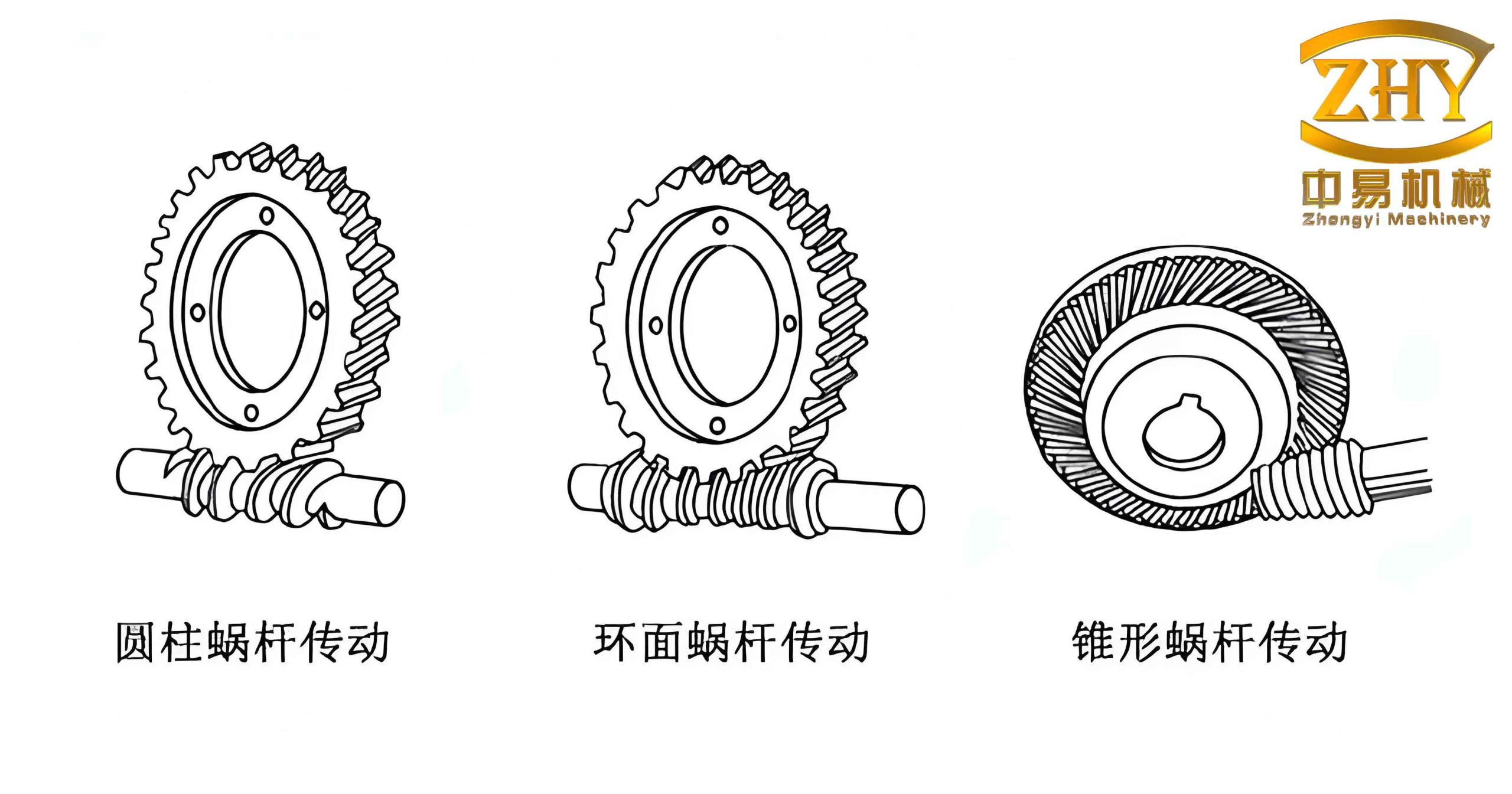
The roller enveloping toroidal worm gear drive consists of a roller worm wheel and a toroidal worm that meshes with it. By converting sliding friction into rolling friction, this drive achieves superior performance. Many researchers have studied the meshing backlash, tooth surface contact stress, and the influence of assembly errors using finite element methods and experimental verification. In this work, I build upon these studies by focusing on the parametric analysis and assembly error effects using a precise three-dimensional model. I present the mathematical derivation, modeling procedure, and detailed numerical results.
Mathematical Model and 3D Precise Modeling
I first establish the coordinate frames for the roller enveloping toroidal worm gear drive. The fixed frame σm (om-xm, ym, zm) is attached to the roller worm wheel, and σn (on-xn, yn, zn) is attached to the worm. The rotating frames σ1 (o1-x1, y1, z1) and σ2 (o2-x2, y2, z2) are attached to the roller worm wheel and worm, respectively, with angular velocities ω1 and ω2, and angular displacements φ1 and φ2. The transmission ratio is i12 = Z2/Z1 = φ1/φ2, where Z1 is the worm thread number and Z2 is the worm gear tooth number. The center distance is a.
The tooth surface equation of the roller worm gear is given by:
$$
\begin{cases}
x_1 = r \cos\theta \\
y_1 = r \sin\theta \\
z_1 = u
\end{cases}
$$
where r is the roller radius, and u and θ are surface parameters of the roller.
The tooth surface equation of the roller enveloping toroidal worm is derived from the envelope condition:
$$
\mathbf{r}_2 = \mathbf{M}_{21} \mathbf{r}_1, \quad f(u,\theta,\phi_1,\phi_2)=0
$$
Specifically, the worm tooth surface can be expressed as:
$$
\begin{aligned}
x_2 &= -a \cos\phi_2 + \left( r \cos\theta \cos\phi_1 – r \sin\theta \sin\phi_1 + a \right) \cos\phi_2 – \left( r \cos\theta \sin\phi_1 + r \sin\theta \cos\phi_1 \right) \sin\phi_2 \\
y_2 &= a \sin\phi_2 + \left( r \cos\theta \cos\phi_1 – r \sin\theta \sin\phi_1 + a \right) \sin\phi_2 + \left( r \cos\theta \sin\phi_1 + r \sin\theta \cos\phi_1 \right) \cos\phi_2 \\
z_2 &= u \\
f &= \left( -a \sin\phi_1 – r \sin\theta \cos\phi_1 + r \cos\theta \sin\phi_1 \right) \sin\phi_2 + \cdots = 0
\end{aligned}
$$
The precise worm gear tooth surface data points are obtained by solving the envelope condition. Using multi-order spline curve fitting, I generate the instantaneous contact lines. Smooth surface fitting of these lines produces the worm tooth surface. A Boolean operation with the worm body yields the accurate three-dimensional model. The resulting model shows line contact between the roller and the worm tooth surfaces.
Effect of Design Parameters on Tooth Surface Contact Characteristics
In engineering applications, the transmission ratio and center distance are often predetermined. For the roller enveloping toroidal worm gear drive, variations in the worm throat minimum diameter dmin and the roller diameter dg affect the tooth surface stress and worm rigidity, thereby influencing the strength and safety factor. I analyze these effects using a fixed transmission ratio i12 = 20 and center distance a = 100 mm.
Influence of Worm Throat Minimum Diameter
I select five values for dmin: 20, 25, 30, 35, and 40 mm. The maximum equivalent stress and minimum safety factor are computed. The results are summarized in Table 1.
| dmin (mm) | 20 | 25 | 30 | 35 | 40 |
|---|---|---|---|---|---|
| Maximum equivalent stress (MPa) | 950 | 890 | 820 | 870 | 980 |
| Safety factor | 0.85 | 0.92 | 1.02 | 0.95 | 0.82 |
The maximum equivalent stress exhibits a “V” shape with respect to dmin, reaching a minimum of 820 MPa at dmin = 30 mm. The safety factor is highest (1.02) at the same diameter. Thus, for this operating condition, dmin = 30 mm is optimal. The relationship can be approximated by a quadratic function:
$$
\sigma_{\text{max}} = 0.5(d_{\text{min}} – 30)^2 + 820
$$
where σmax is in MPa. This formula is valid within the range 20–40 mm.
Influence of Roller Diameter
I consider three roller diameters: dg = 16, 18, and 20 mm, while keeping dmin = 30 mm. The maximum equivalent stress and minimum safety factor are presented in Table 2.
| dg (mm) | 16 | 18 | 20 |
|---|---|---|---|
| Maximum equivalent stress (MPa) | 1000 | 1150 | 1350 |
| Minimum safety factor | 0.90 | 0.75 | 0.60 |
The maximum equivalent stress increases with roller diameter, while the safety factor decreases. The smallest roller diameter (16 mm) yields the lowest stress and highest safety factor. The stress variation can be described by a linear relationship:
$$
\sigma_{\text{max}} = 87.5 d_g – 400
$$
where dg is in mm and σmax in MPa. Therefore, for high load capacity, a smaller roller diameter is preferred.
Effect of Assembly Errors on Tooth Surface Meshing Backlash
Assembly errors directly affect the tooth surface normal clearance or interference. I analyze four types of errors: center distance error, worm axial error, worm gear axial error, and shaft intersection angle error. The positive direction for each error is defined as increasing the parameter.
Center Distance Error
I vary the center distance error Δa from –0.1 mm to +0.1 mm. The resulting normal clearance (positive) or interference (negative) for the first and second tooth pairs is given in Table 3.
| Δa (mm) | –0.10 | –0.05 | 0 | +0.05 | +0.10 |
|---|---|---|---|---|---|
| First tooth pair | –0.06 | –0.03 | 0 | +0.02 | +0.05 |
| Second tooth pair | –0.09 | –0.05 | 0 | +0.04 | +0.08 |
Negative values indicate interference (overlap). As Δa decreases, interference increases. The second tooth pair is more sensitive. To maintain zero backlash, the center distance error should be kept within ±0.05 mm. The relationship can be expressed as:
$$
\delta = k_1 \Delta a + c
$$
where δ is the normal clearance, and k1 is approximately –0.6 for the first pair and –0.9 for the second pair.
Worm Axial Error
Due to symmetry, I consider only one direction of worm axial displacement Δl1 from 0 to 0.05 mm. The clearances on the left and right sides are listed in Table 4.
| Δl1 (mm) | 0 | 0.01 | 0.02 | 0.03 | 0.04 | 0.05 |
|---|---|---|---|---|---|---|
| Left first pair | 0 | –0.01 | –0.02 | –0.03 | –0.04 | –0.05 |
| Left second pair | 0 | –0.01 | –0.02 | –0.03 | –0.04 | –0.05 |
| Right first pair | 0 | +0.01 | +0.02 | +0.03 | +0.04 | +0.05 |
| Right second pair | 0 | +0.01 | +0.02 | +0.03 | +0.04 | +0.05 |
The worm axial error creates a linear variation of interference on one side and clearance on the opposite side. The magnitude of change is approximately equal to the displacement. To ensure backlash-free performance, the worm axial mounting error must be within ±0.03 mm. The relationship for each side is:
$$
\delta_{\text{left}} = – \Delta l_1, \quad \delta_{\text{right}} = + \Delta l_1
$$
Worm Gear Axial Error
The worm gear axial displacement Δl2 is varied from 0 to 0.25 mm. The clearances are presented in Table 5.
| Δl2 (mm) | 0 | 0.05 | 0.10 | 0.15 | 0.20 | 0.25 |
|---|---|---|---|---|---|---|
| Left first pair | 0 | –0.01 | –0.02 | –0.03 | –0.04 | –0.05 |
| Left second pair | 0 | –0.01 | –0.02 | –0.03 | –0.04 | –0.05 |
| Right first pair | 0 | +0.01 | +0.02 | +0.03 | +0.04 | +0.05 |
| Right second pair | 0 | +0.01 | +0.02 | +0.03 | +0.04 | +0.05 |
The worm gear axial error has a relatively small effect on the meshing zone. The interference increases linearly on one side and decreases on the other, but the magnitude is only about 20% of the displacement. For ensuring backlash-free performance, the worm gear axial error should be limited to within ±0.2 mm. The sensitivity factor is approximately 0.2.
Shaft Intersection Angle Error
The shaft intersection angle error Δγ is varied from –0.5° to +0.5°. The normal clearances for the first and second tooth pairs are given in Table 6.
| Δγ (°) | –0.5 | –0.4 | –0.3 | –0.2 | –0.1 | 0 | +0.1 | +0.2 | +0.3 | +0.4 | +0.5 |
|---|---|---|---|---|---|---|---|---|---|---|---|
| First pair | +0.03 | +0.02 | +0.02 | +0.01 | 0 | 0 | –0.01 | –0.02 | –0.03 | –0.04 | –0.05 |
| Second pair | +0.04 | +0.03 | +0.02 | +0.02 | +0.01 | 0 | –0.01 | –0.02 | –0.03 | –0.04 | –0.06 |
Positive Δγ (rotation clockwise) causes interference (negative clearance) on the tooth surfaces, while negative Δγ introduces clearance. The change in normal clearance is approximately 0.07 mm over the range of –0.5° to +0.5°. The second tooth pair is slightly more sensitive. To maintain zero backlash, the shaft intersection angle error should be controlled within ±0.4°. The relationship can be approximated by:
$$
\delta = -0.14 \cdot \Delta\gamma
$$
where Δγ is in degrees and δ in mm.
Conclusion
In this work, I established a mathematical and three-dimensional precise solid model for a roller enveloping toroidal worm gear drive. The influence of design parameters—worm throat minimum diameter and roller diameter—on tooth surface contact characteristics was systematically analyzed. The results reveal that the maximum equivalent stress as a function of worm throat minimum diameter follows a “V” shape, with an optimal value at 30 mm for the given conditions. The roller diameter has a monotonic effect: smaller diameters reduce stress and increase safety factor. For assembly errors, center distance error and worm axial error cause significant normal clearance or interference, requiring tight tolerances of ±0.05 mm and ±0.03 mm respectively. Worm gear axial error and shaft intersection angle error affect the meshing zone asymmetrically, but their influence is less severe, with recommended tolerances of ±0.2 mm and ±0.4° respectively. These findings provide practical guidelines for the design and assembly of high-precision roller enveloping toroidal worm gear drives, ensuring optimal contact performance and long service life.