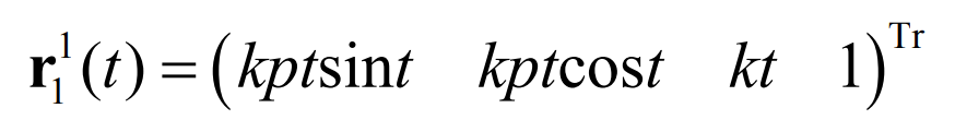
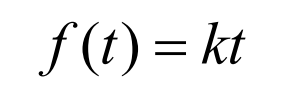
Spiral bevel gear cone equidistant helix is characterized by the rotation of helix, radial motion and axial motion. These three motions form a linear relationship with each other Γ 1 equation is as follows:
Because the curvature and torsion are not fixed values, the equidistant helix of the conical surface of spiral bevel gear does not belong to a kind of helix in mathematics. However, equidistant helix and equiangular helix have great acquaintance in form. Therefore, for convenience, they are still called helix.
Where p = Tan( δ) ,δ Is the sub cone angle, and K is the fixed value.
According to the comparison formula, for the equal angle helix, there are:
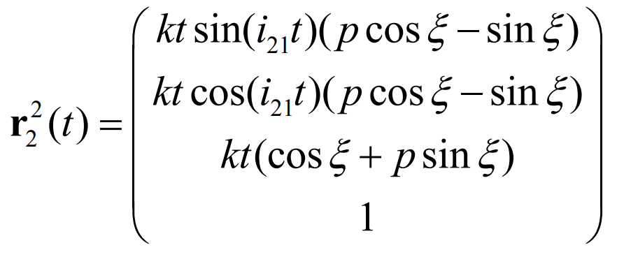
At the same time, P is the same in the two equations. By substituting the formula, we can get Γ 2 equation:
According to the geometric parameters, we can get:
In the general discussion of pure rolling contact conjugate curve bevel gear, the section curve Γ S1 and Γ The specific shape of S2 is not limited. Therefore, the section curve can still be designed as a double segment arc like a pure rolling contact equiangular spiral bevel gear.
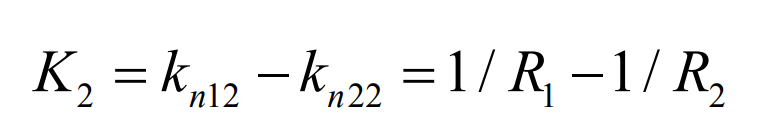
Similar to pure rolling contact equal angle spiral bevel gear, let kn12 = 1 / R1, kn22 = 1 / R2. :
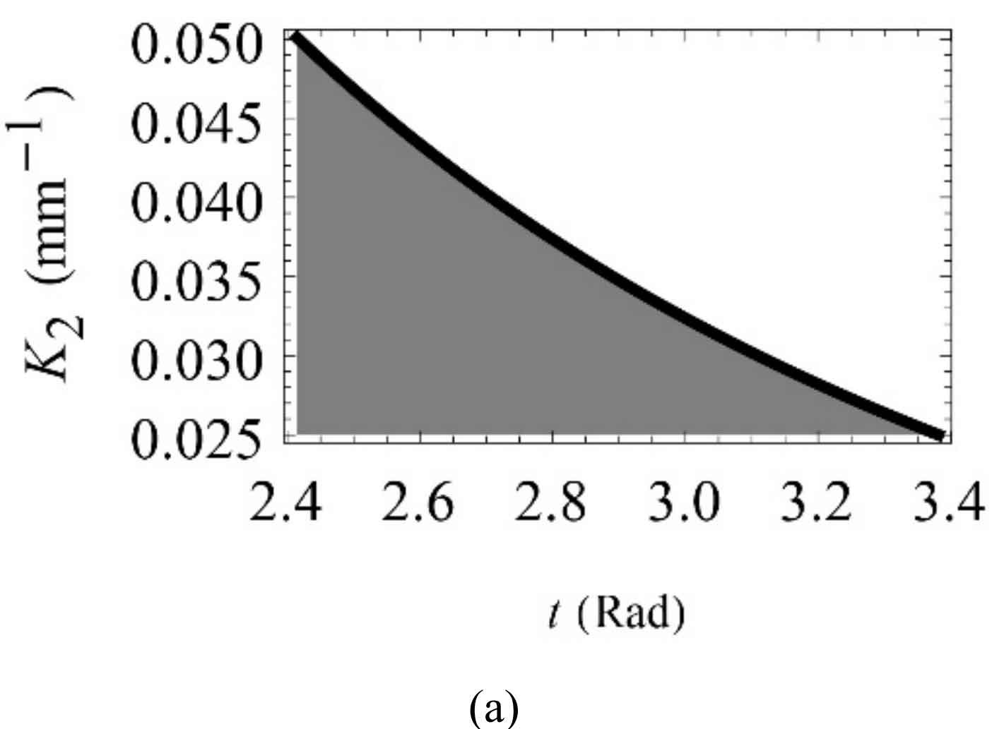
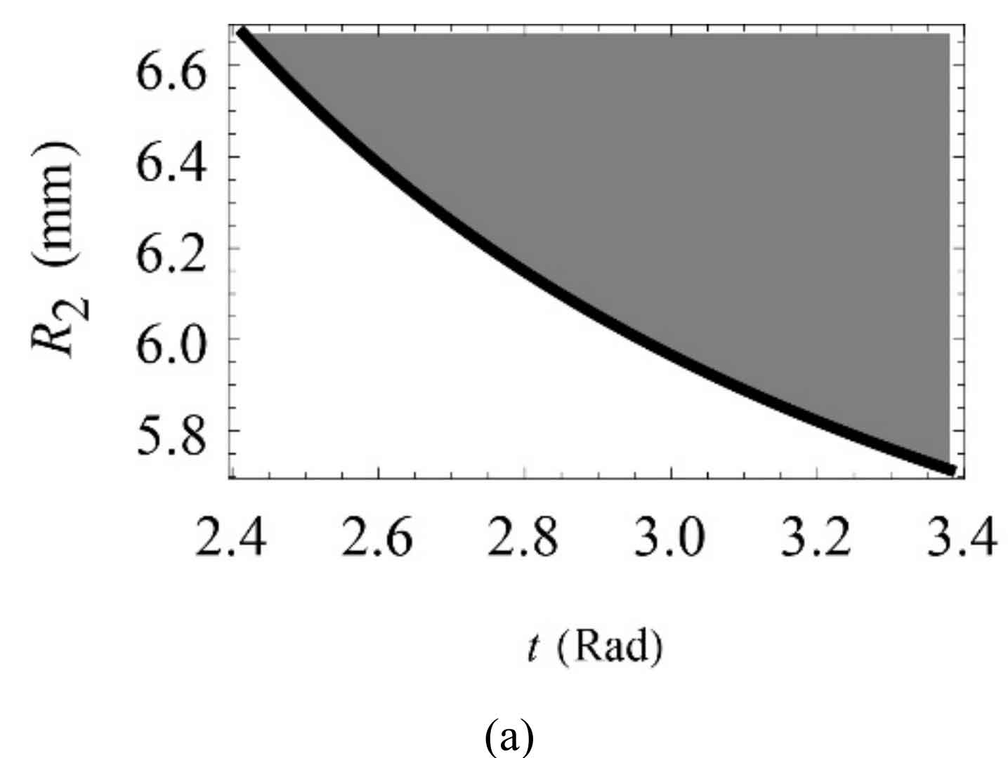
According to the geometric design parameters of large and small gears, the value range of concave tooth and convex tooth side K2 of equidistant spiral bevel gear pinion can be obtained from the formula, as shown in the gray part of Figure 1.
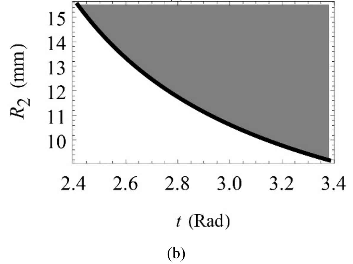
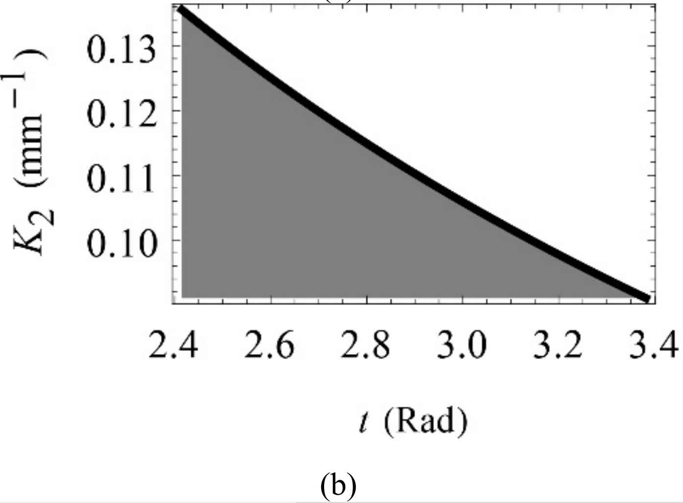
Similarly, similar to the pure rolling contact equiangular spiral bevel gear, set R1 = 5mm first, and the value range of R2 can be obtained from the formula, as shown in the gray part of Figure 2. In order to make the concave tooth side and convex tooth side have the same normal section tooth profile, R2 = 17mm is taken. Finally, based on the tooth surface forming method and the design of large and small gears
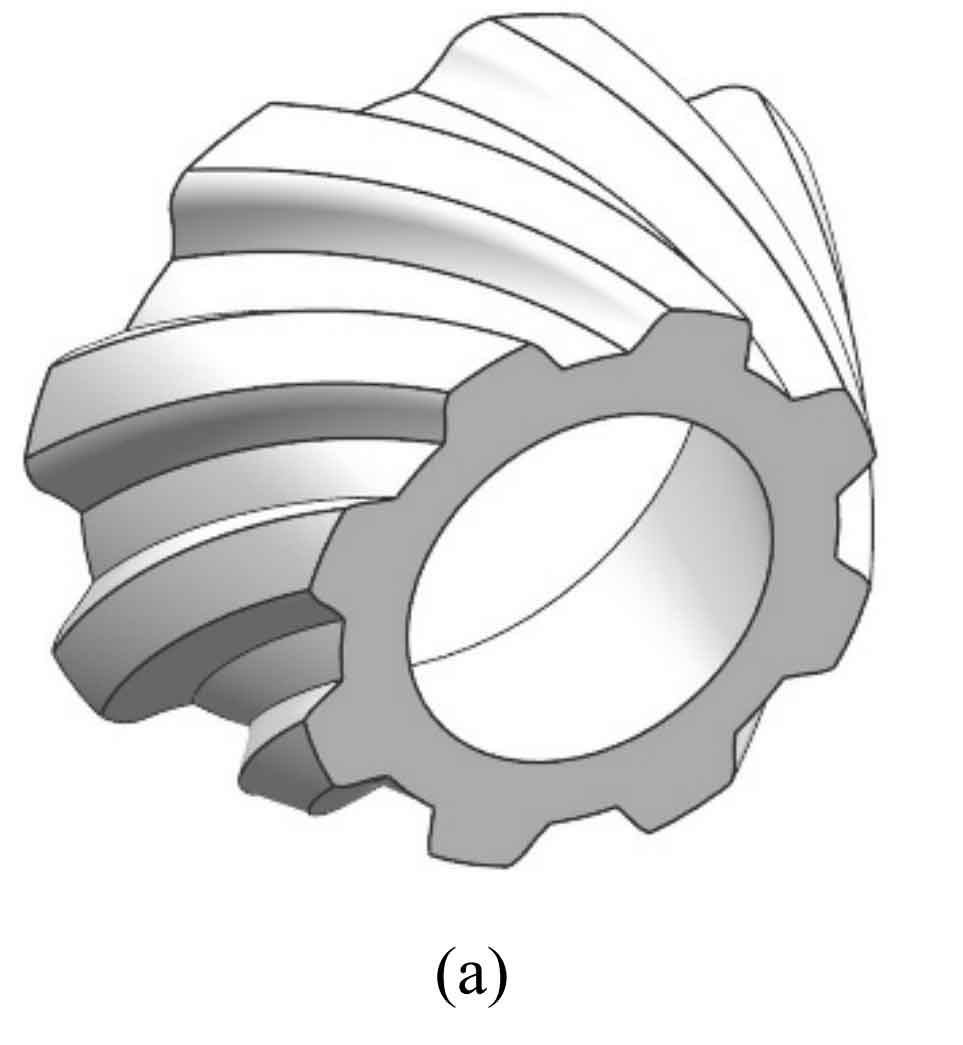
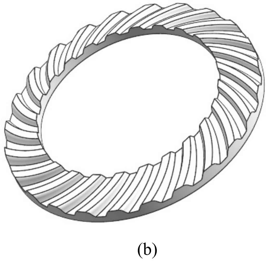
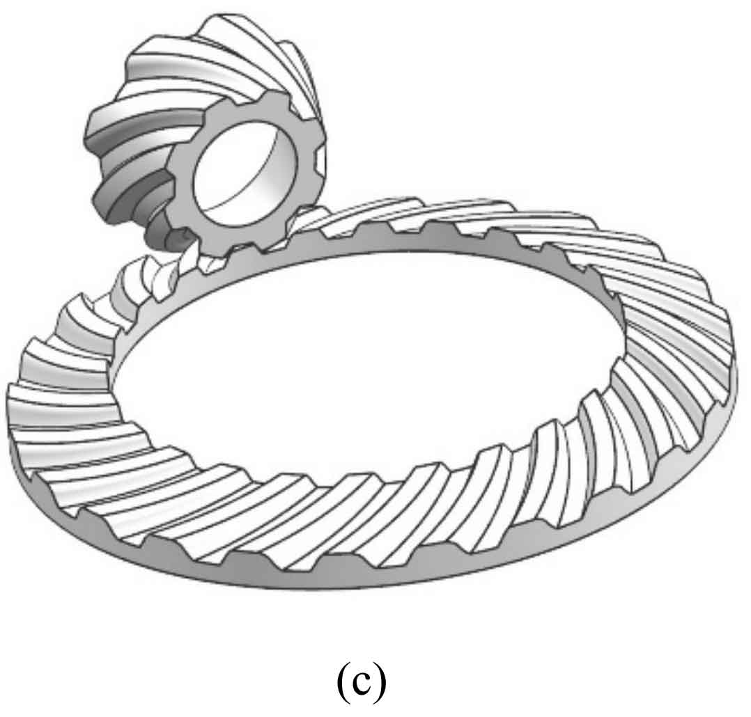
According to the design parameters, the solid tooth profile of large and small gears can be constructed. Figure 3 shows the built solid model of large and small gears. Each tooth surface of the model consists of 100 × 40 points are fitted.
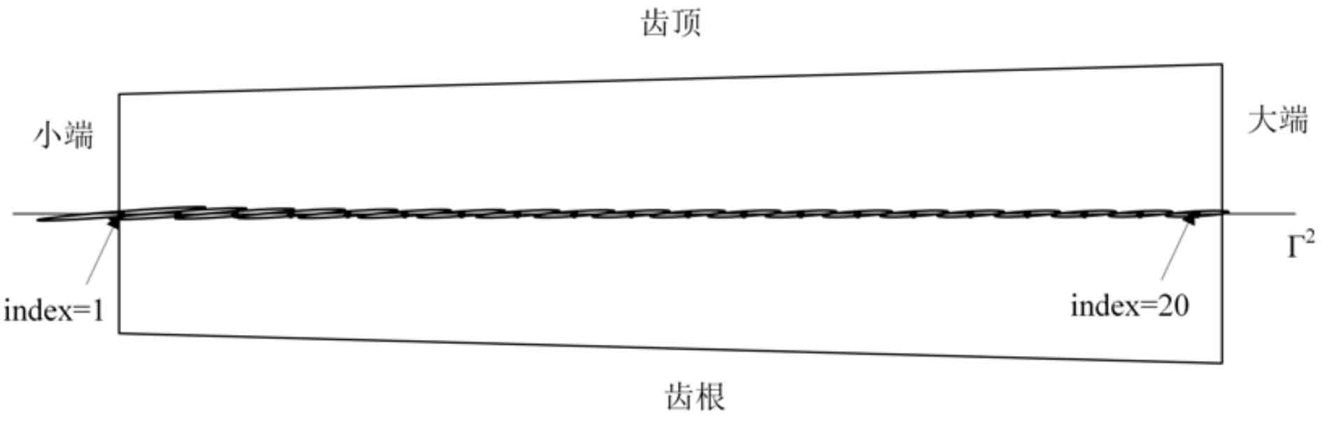
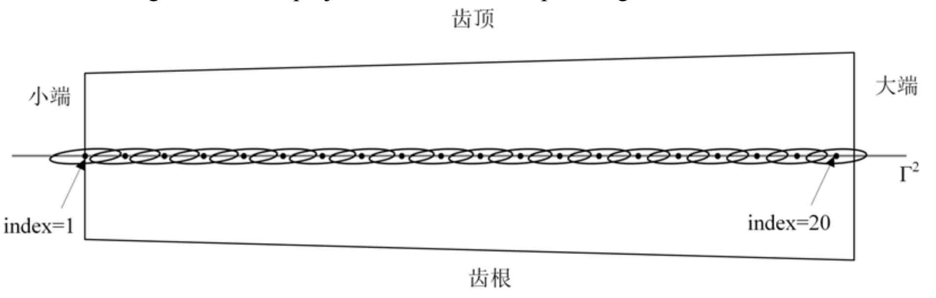
because Γ 1, Γ In fact, they are Σ 1, Σ 2 upper contact trace, composed of K1, K2, τ 12 and formula, the two principal values of relative normal curvature, KP1 and KP2, and the angle between the long axis of the contact ellipse and the contact trace can be calculated η 1。 The calculated KP1, KP2 and η 1 value. Figures 4 and 5 show the movement of the instantaneous contact ellipse on the large and small gears.