
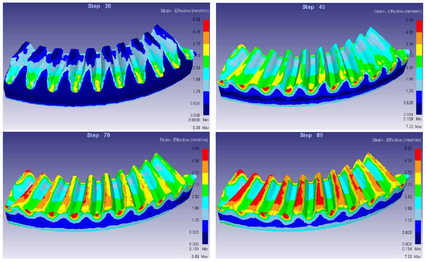
As shown in the figure, the equivariant distribution diagram of five spiral bevel gear blank size schemes is shown, in which (a) (b) (c) (d) (e) corresponds to the equivariant distribution diagram of five groups of simulation experiments with inner diameter of 125 mm and outer diameter of 160 mm, 165 mm, 170 mm, 175 mm and 180 mm respectively. It can be seen from the figure that the distribution of equivalent strain in the forming process of spiral bevel gear blanks of various sizes is basically the same.
The part with larger equivalent effect is always distributed in the tooth shape, but the distribution of strain is constantly changing. When the upper die starts to move down, the place with large strain is the tooth root of the spiral bevel gear blank. At this time, the contact surface between the upper die and the spiral bevel gear blank is the tooth root surface of the forging. With the continuous downward movement of the upper die, the metal of the spiral bevel gear blank flows into the upper die cavity. At this time, the equal effect change at the tooth top gradually increases and even exceeds the equal effect change at the tooth root. Until the die closing is completed, the equal effect change at the tooth top reaches the maximum, while the equal effect change at the tooth root remains basically unchanged in the whole process.
| Blank outer diameter (mm) | 160 | 165 | 170 | 175 | 180 |
| Maximum equivalent strain (mm / mm) | 26 | 21.7 | 18.9 | 14.7 | 17.8 |
The maximum equivalent strain values of five groups of spiral bevel gear blank size schemes are listed in the table. Through analysis, it can be concluded that (a) (b) (c) (d) in the four groups of simulation schemes, the outer diameter of spiral bevel gear blank is less than the outer diameter of the upper surface of the lower die, and the spiral bevel gear blank is in direct contact with the upper surface of the lower die. At this time, the maximum equivalent strain decreases with the increase of spiral bevel gear blank size. (e) The outer diameter of the experimental blank is 180 mm, which is slightly larger than the outer diameter of the upper surface of the lower die. The spiral bevel gear blank is in contact with the inclined side of the lower die, resulting in friction between the blank and the side of the lower die when the upper die moves downward, and the equal effect variable becomes larger. The spiral bevel gear blank is easy to form barbs and wear the die.
Based on the above stroke load curve analysis, equivalent stress analysis and equal effect variation analysis, the maximum load and the maximum equivalent stress are basically the same in the process of precision forging spiral bevel gear from spiral bevel gear blanks of different sizes, and the value is relatively small, while the scheme with the outer diameter of spiral bevel gear blank of 175 mm is the smallest, Therefore, the optimal scheme selected in this group of experiments is the spiral bevel gear blank with inner diameter of 125 mm, outer diameter of 175 mm, height of 33.5 mm and upper surface cone angle of 18 °.