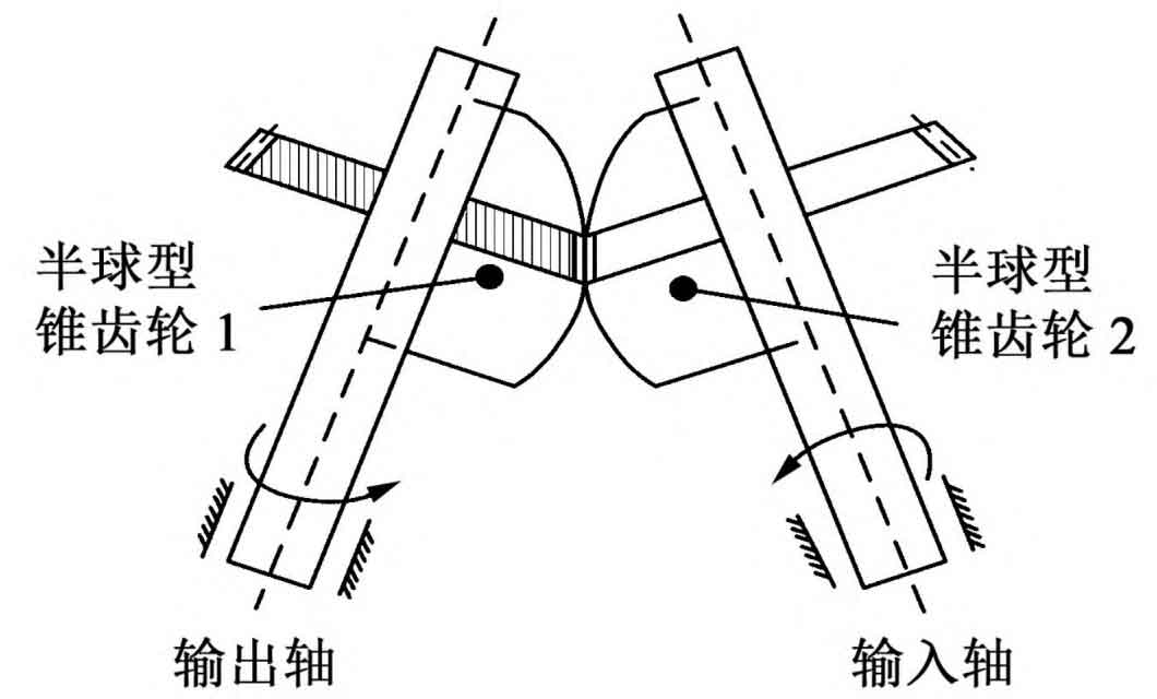
The transmission model of the flexible hemispherical bevel gear is shown in Figure 1. The hemispherical bevel gear 2 is fixedly connected with the input shaft, and the hemispherical bevel gear 1 is fixedly connected with the output shaft.

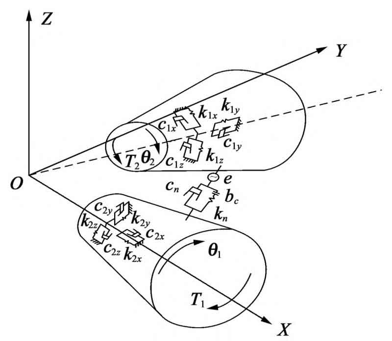
Operate according to the direction shown in Figure 1, take the meshing pair on both sides as the research object for force analysis, and establish the coordinate system as shown in Figure 2, with the output hemispherical bevel gear shaft as the X axis. Regardless of tooth surface friction and torsional vibration, the dynamic meshing force in the normal direction between tooth surfaces is decomposed in the radial, tangential and axial directions during the gear transmission process. The forces in the three directions resulting from the decomposition cause the gear system to vibrate, including the transverse, axial and torsion on the meshing line. Using the rigid-flexible coupling operation mode, ignoring the impact of the elastic deformation of the two gear support shafts on the meshing performance of the hemispherical bevel gear system, the dynamic analysis model of the hemispherical bevel gear transmission system is obtained by using the lumped parameter method (Figure 2). The direction of torsion is counterclockwise.

In Figure 2, kn and cn are the meshing stiffness and meshing damping of the hemispherical bevel gear 1 and the hemispherical bevel gear 2 respectively; Kix, kiy, kiz and cix, ciy, ciz are respectively the meshing stiffness and meshing damping of the hemispherical bevel gear i along the X axis, Y axis and Z direction (i=1,2); Bc is the tooth side clearance; T1 and T2 are input torque and load torque respectively.
The intersection angle of the hemispherical bevel gear shaft is:

Where, β Is the independent variable of the hemispherical bevel gear, with the range of 0 °~80 °.
The generalized displacement array of the system can be expressed as:

The normal meshing force Fn of meshing gear pair is expressed as:

Where, λ N is the relative displacement in the normal direction of the meshing point of the gear due to vibration and error.
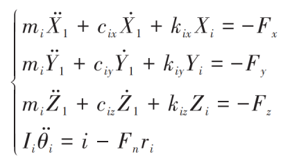
The differential equation of the dynamic model of the hemispherical bevel gear is:

Where, i=1,2; Fx, Fy and Fz are the components of Fn along the coordinate direction; Ii is the rotational inertia of two hemispherical bevel gears. Elimination of torsional displacement θ 1 and θ 2. We can get:

Where, me is the equivalent mass of the gear pair; Fp is the circumferential force of the driving hemispherical bevel gear.
The dynamic response of the system can be obtained by dimensionally normalizing the above equations and solving them by Runge-Kutta method, which is compared with the simulation results.
